Assembly and Installation
FLOWSIC100 Flare · Operating Instructions · 8013344/11L2/V 2-5/2018-10 · © SICK Engineering GmbH 137
Subject to change without notice
Connecting device type FLSE100 EX/EX-RE
– S/R units: Ex zone 1 without Exe terminal compartment, CSA CI I, Div1/Div2
– MCUP: without explosion protection, Ex Zone 2 or CSA CI I, Div2 or CSA CI I, Div1
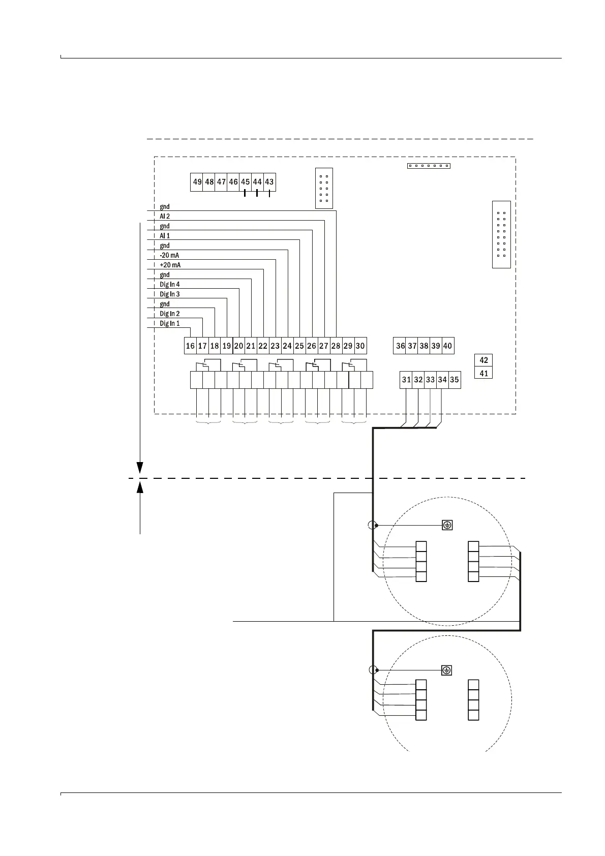
Fig. 67 FLOWSIC100 EX/EXRE cabling
RS485a
RS485b
br
ws
gn
ge
+24 V DC
GND
a-unit A
b-unit A
ws
br
gn
ge
1 2 3 4 5 6 7 8 9 10 11 12 13 14 15
com
n.c.
n.o.
com
n.c.
n.o.
com
n.c.
n.o.
com
n.c.
n.o.
com
n.c.
n.o.
MCUP processor board
Ex zone Safe area (or Ex zone 2 for MCUP in Ex zone 2 or CSA CI I, Div2 or CSA CI I, Div1
on-site cabling in explosion
protected version according
to
→
p. 122, 3.8.3
Terminal compartment
Terminal compartment
(Contact position in current-free state)
Note
For 2-path, 2x1-path or 3x1-path measurement, the
second /third FLSE master and FLSE slave are
connected by use of a junction box with Ex
certification (available from SICK on request) to the
MCUP.
”Point-to-point” wiring for 2-path and 2x1-path
measurement on request.
* MCUP Ex zone 2 only
yellow
green
white
brown
brown
white
green
yellow
white
brown
green
yellow
brown
white
green
yellow
A Operation/malfunction
B Maintenance
C Check cycle
D Maintenance request
E Limit value
A
BCD
E
Service
RS485*
gnd B A
Connection display
Connection Interface module