30 FLOWSIC100 Flare · Operating Instructions · 8013344/11L2/V 2-5/2018-10 · © SICK Engineering GmbH
Product Description
Subject to change without notice
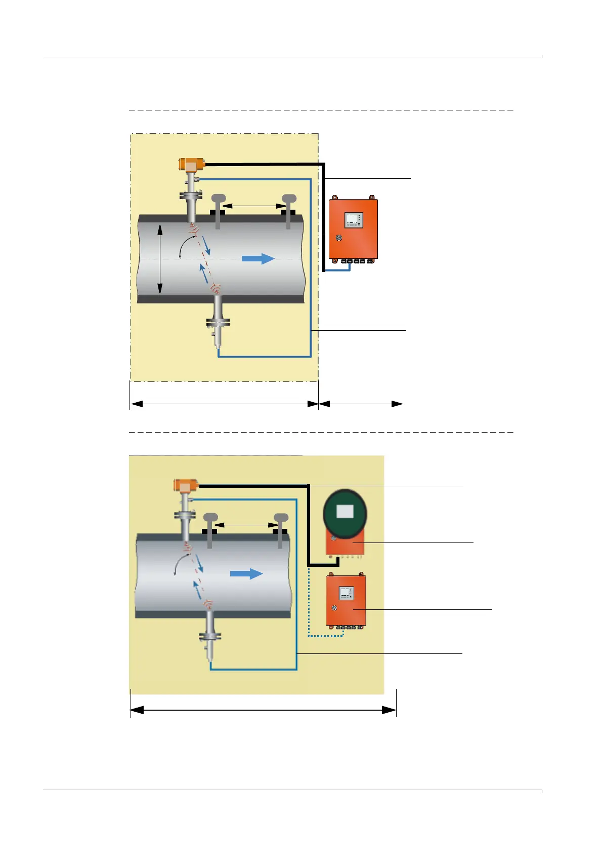
System overview of cross-duct version (example: FLOWSIC100 EX-S)
Fig. 3 System overview, horizontal installation, FLOWSIC100 EX-S, MCUP without explosion protection
Fig. 4 System overview, horizontal installation, FLOWSIC100 EX-S, MCUP explosion protected
POWER
FAILURE
MAINTENANCE
REQUEST
MCUP control unit
without explosion
protection
Sender/receiver unit
FLSE100-EXS Master
Sender/receiver unit
FLSE100-EXS Slave
Connection cable
Connection cable
α
Potentially explosive atmosphere zone 1 or zone 2 Safe area
D
3 D
Pressure Temperature
sensor sensor
Potentially explosive atmosphere zone 1 or zone 2
Sender/receiver unit
FLSE100-EXS Master
Sender/receiver unit
FLSE100-EXS Slave
α
Connection cable
MCUP control unit
certified for Ex zone 1
and Ex zone 2
MCUP control unit
certified only for Ex zone 2
Connection cable
3 D
Pressure Temperature
sensor sensor