96 FLOWSIC100 Flare · Operating Instructions · 8013344/11L2/V 2-5/2018-10 · © SICK Engineering GmbH
Assembly and Installation
Subject to change without notice
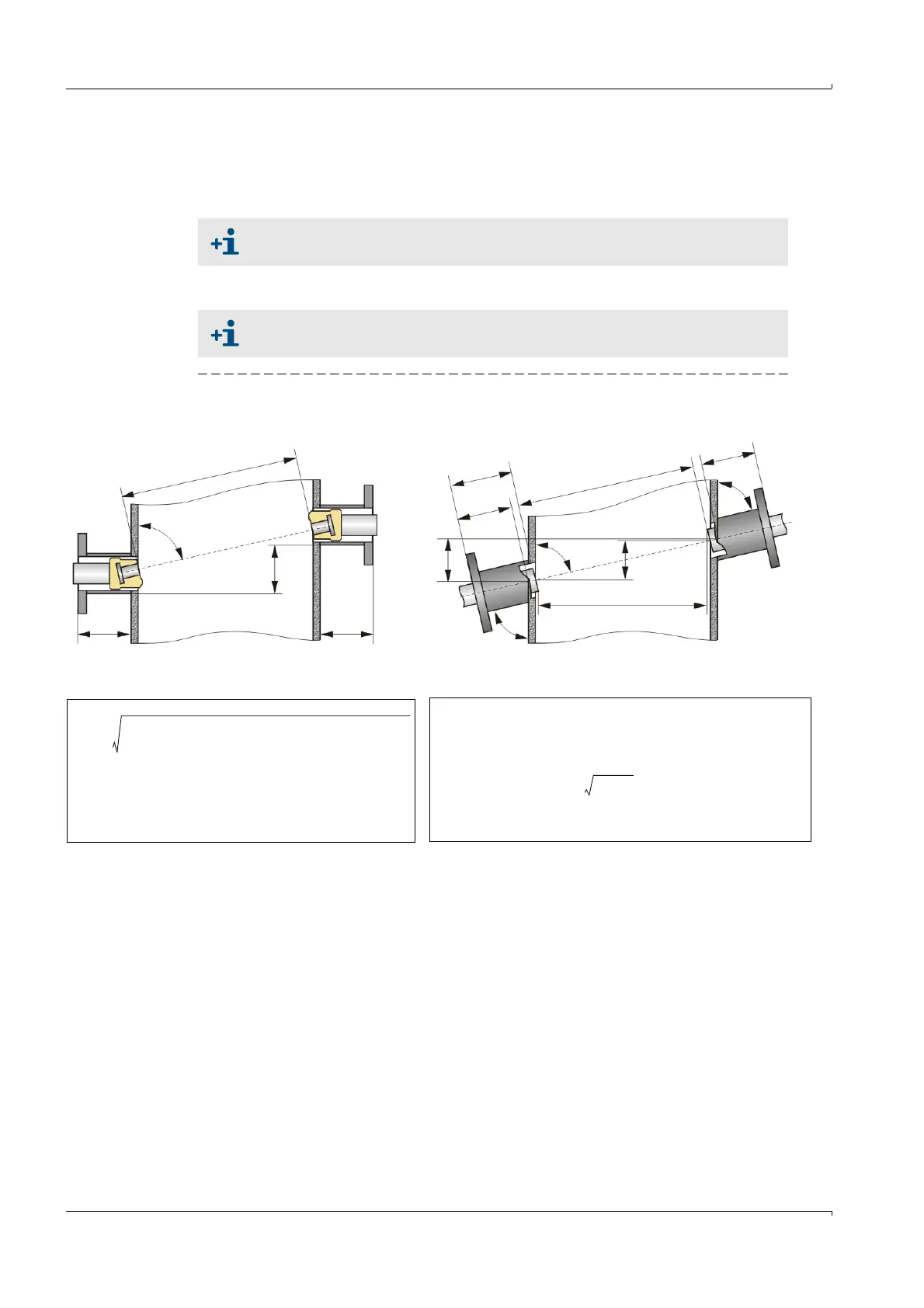
3.3.1.4 Determine path angle and path length
Exact values for path angle and length must calculated using the geometric data to keep
measuring inaccuracy as low as possible (
→
Fig. 43,
→
pg. 97, Fig. 44). Enter these values in
the device as parameters during start-up
→
pg. 167, § 4.2.2(.).
Cross-duct versions
Fig. 43 for non-retractable sender/receiver units
A software to perform the geometry calculations can be found on the Product
CD.
Path angle for exact nozzle assembly 77.5 °
d = Off-center probes distance = 4.9 mm (manufacturer's specification)
U = Pipeline circumference at assembly location
S = Seal thickness = 4 mm
NL = Probe nominal length (manufacturer's specification)
D1, D2 = effective nozzle length (
→
pg. 93, Fig. 42)
a = Nozzle offset (
→
pg. 86, § 3.3.1.1)
f = 1 for 1-path measurements, 0.8 for 2-path measurements
La2d•–()
2 U
π
----
D1 D2 2 S• 2NL•–+++
2
+=
α
U
π
----
08,• D1 D2 2 S• 2NL•–+++
a2d•–
-----------------------------------------------------------------------------------------
atan=
La2d•–()
2 U
π
----
f• D1 D2 2 S• 2NL•–+++
2
+=
α
U
π
----
f• D1 D2 2 S• 2NL•–+++
a2d•–
----------------------------------------------------------------------------------
atan=
D1
D2
L
α
a
FLSE100-EXS FLSE100-EX, FLSE100-EXRE
a
D
1
L
D
2
N
L
b
α
β1
β2
Setpoint value for β1 and β2 = 75 °
k
Lb
2
k
2
+=
α
k
b
---
atan=
b a NL D1–S–()β1cos•–NLD2–S–()β2cos•–=
k
U
π
----
f• NL D1–S–()β1sin•–NLD2–S–()β2sin•–=