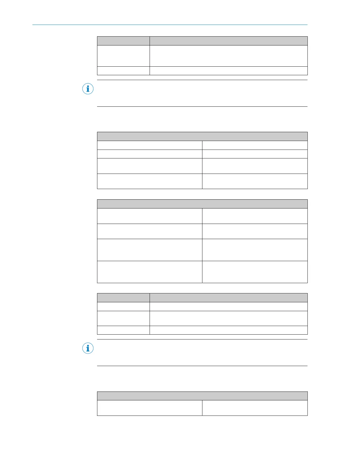
Function Notes
Series connec‐
t
ion/cascading
If emergency stop pushbuttons are connected in series, the maximum
conductor resistance must not exceed 100 Ω (see "Technical data",
page 130).
Discrepancy time See the report in the configuration software
NOTE
Y
ou will find more information in the operating instructions for the ES21 emergency
stop pushbutton.
5.4.1.2 Electro-mechanical safety switches and locking devices
Table 51: Connection of electro-mechanical safety switches
Electrical connection: example with FX3-XTIO
Single-channel, at 24 V Contact between 24 V and I1
Single-channel, at test output Contact between X2 and I2
Dual-channel, at 24 V Channel 1: contact between 24 V and I3
Channel 2: contact between 24 V and I4
Dual-channel, at test output Channel 1: contact between X1 and I5
Channe
l 2: contact between X2 and I6
Table 52: Connection of locking devices
Electrical connection: example with FX3-XTIO
Single-channel, at 24 V Contact between 24 V and I1
C
oil at Q1
Single-channel, at test output Contact between X1 and I1
C
oil at Q1
Dual-channel, at 24 V Channel 1: contact between 24 V and I1
Channe
l 2: contact between 24 V and I2
Coil at Q1
Dual-channel, at test output Channel 1: contact between X1 and I1
Channe
l 2: contact between X2 and I2
Coil at Q1
Table 53: Functions with electro-mechanical safety switches and locking devices
Function Notes
Tested Possible
Series connec‐
t
ion/cascading
If safety switches are connected in series, the maximum conductor
resistance must not exceed 100 Ω (see "Technical data", page 130).
Discrepancy time See the report in the configuration software
NOTE
Y
ou will find more information in the operating instructions for the electro-mechanical
safety switches.
5.4.1.3 Enabling switch E100
Table 54: Connection of the E100
Electrical connection: example with FX3-XTIO
2 positions, at 24 V Channel 1: contact E31 between 24 V and I1
Channe
l 2: contact E41 between 24 V and I2
ELECTRICAL INSTALLATION 5
8012478/1IG6/2023-02-24 | SICK O P E R A T I N G I N S T R U C T I O N S | Flexi Soft Modular Safety Controller
79
Subject to change without notice