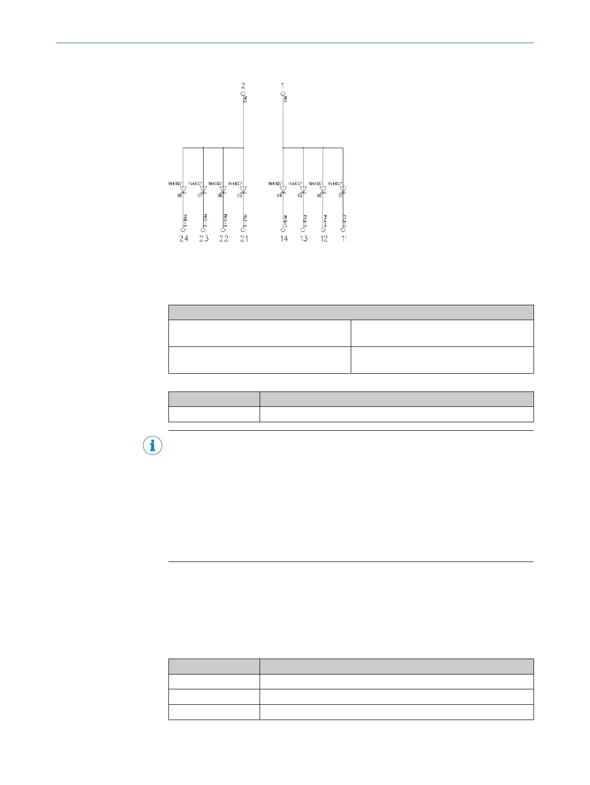
Internal circuitry for diode module DM8-A4K
Figure 50: Internal circuitry for diode module DM8-A4K
5.4.1.7 Operating mode selector switch
Table 62: Connection of operating mode selector switch
Electrical connection: example with FX3-XTIO
Operating mode selector switch (1 of 2), at 24
V
Channel 1: contact between 24 V and I1
Channe
l 2: contact between 24 V and I2
Operating mode selector switch (1 of 2), at test
out
put
Channel 1: contact between X1 and I1
Channel 2: contact between X1 and I3
Table 63: Function with operating mode selector switch
Function Notes
Tested Possible
NOTE
•
Oper
ating mode selector switches without test signals support between 2 and
8 operating modes; operating mode selector switches with test signals support
between 2 and 4 operating modes.
•
When wiring the tested operating mode selector switch, please remember that if
you are using a test output with an odd number (X1, X3, X5, X7), inputs with odd
numbers (I1, I3, I5, I7) must be used; if you are using a test output with an even
number (X2, X4, X6, X8), inputs with even numbers (I2, I4, I6, I8) must be used.
•
You will find more information in the operating instructions for the operating mode
selector switches.
5.4.1.8 Volt-free contacts
The configuration software provides a range of volt-free contacts for “free” arrangement
of cont
act elements. This enables a variety of N/C / N/O combinations to be imple‐
mented with and without testing. There are also start and stop button, reset button,
and external device monitoring (EDM) elements available.
Table 64: Functions with volt-free contacts
Function Notes
Tested Possible
Series connection Possible
Discrepancy time See the report in the configuration software
ELECTRICAL INSTALLATION 5
8012478/1IG6/2023-02-24 | SICK O P E R A T I N G I N S T R U C T I O N S | Flexi Soft Modular Safety Controller
83
Subject to change without notice