Electrical connection
T
able 61: Connection of multiple pressure-sensitive safety mats with diode module DM8-A4K
connected upstream
Electrical connection: example with FX3-XTIO or FX3-XTDI
Pressure-sensitive safety mat which triggers a
shor
t-circuit in 4-conductor technology, at test
output and with diode module DM8-A4K con‐
nected upstream
Channel 1: Contact from X1 to I1 via diode
Channel 2: Contact from X2 to I2 via diode
Channels 3 to 8 as shown in the
circuit diagram: see figure 48, page 82
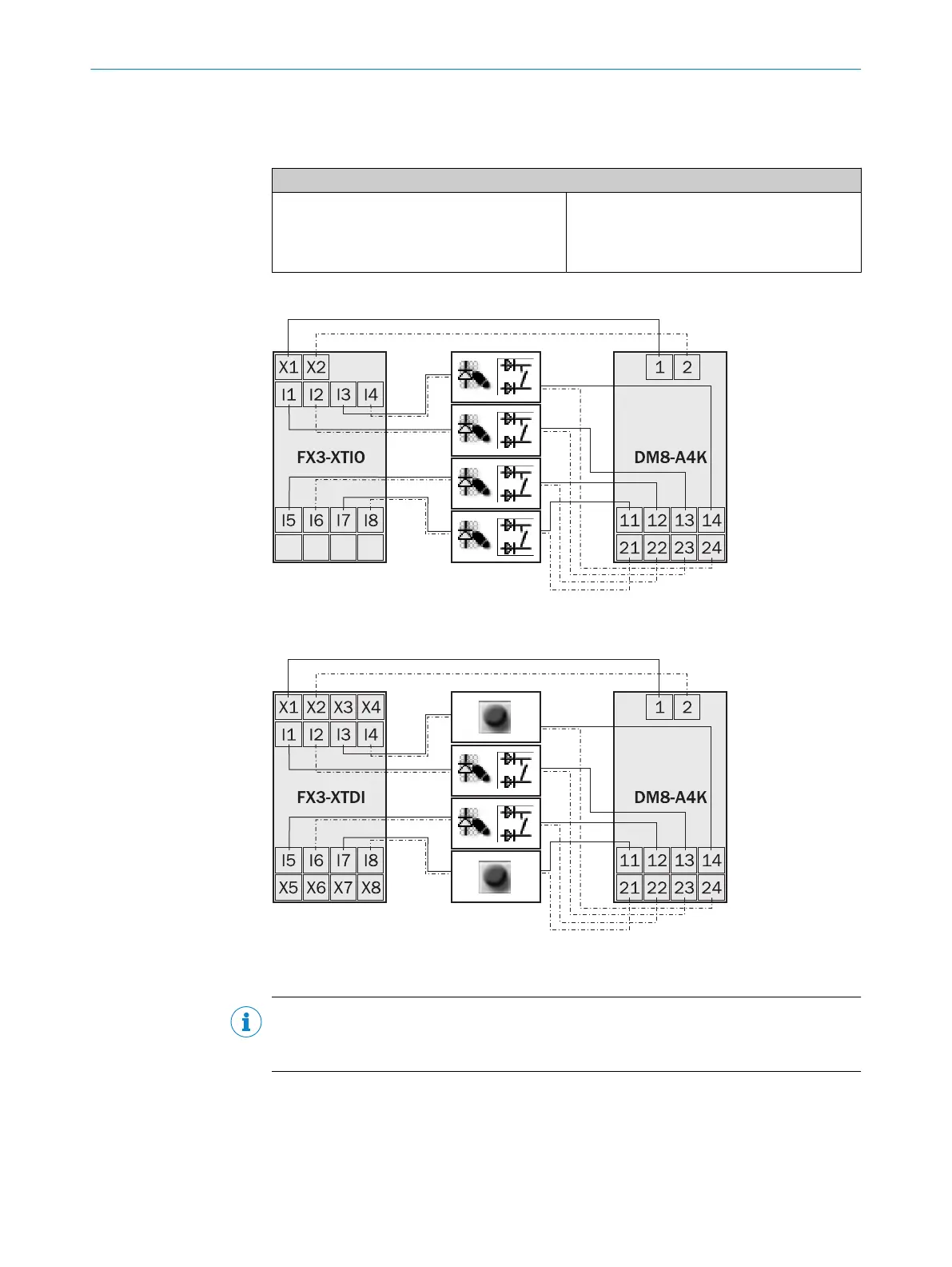
Circuit diagrams
Figure 48: Circuit diagram for multiple pressure-sensitive safety mats with diode module DM8-
A4K c
onnected to the FX3-XTIO upstream
Figure 49: Circuit diagram for multiple pressure-sensitive safety mats with diode module DM8-
A4K c
onnected to the FX3-XTDI upstream
NOTE
Ins
tead of a pressure-sensitive safety mat, you can also connect a safety switch or an
emergency stop pushbutton, for example (see figure 49, page 82).
5 ELECTRICAL INSTALLATION
82
O P E R A T I N G I N S T R U C T I O N S | Flexi Soft Modular Safety Controller 8012478/1IG6/2023-02-24 | SICK
Subject to change without notice