Approach
1.
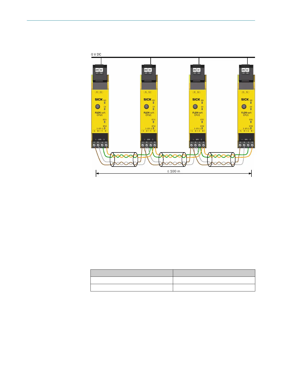
Connect the identically named terminals with each other (e.g. EFI1_A at station A
with EFI1_A at station B etc.).
Figure 59: Connecting Flexi-Link stations via EFI1+2
2. Connect not used cables to the functional earth (FE) at both ends.
3.
Connect all connected Flexi Link stations with the same GND connection of the
voltage supply (terminal A2 on the system plug).
Complementary information
Connection:
•
No external terminator is required for the EFI connections on the main module.
•
Stub cables or star-shaped wiring are not allowed.
•
The maximum permissible total length of the cables for EFI1 and EFI2 (all stations)
is 100m each.
Flexi-Link cables:
•
Flexi-Link stations can be connected using CAN cables (shielded, twisted pair).
Table 78: Possible lengths of cable and types for Flexi-Link connections
Length of cable Cable type
Up to 40m 2 × 2 × 0.25mm² (AWG 23)
Up to 100m 2 × 2 × 0.34mm² (AWG 22)
•
SIC
K offers a suitable cable for connections up to 100m (SICK part number
6034249, 2 × 2 × 0.34mm², sold by the meter, see "Accessories for the safety
controller", page 182).
Further topics
•
"EMC me
asures for Flexi Link and Flexi Line", page 101
ELECTRICAL INSTALLATION 5
8012478/1IG6/2023-02-24 | SICK O P E R A T I N G I N S T R U C T I O N S | Flexi Soft Modular Safety Controller
99
Subject to change without notice