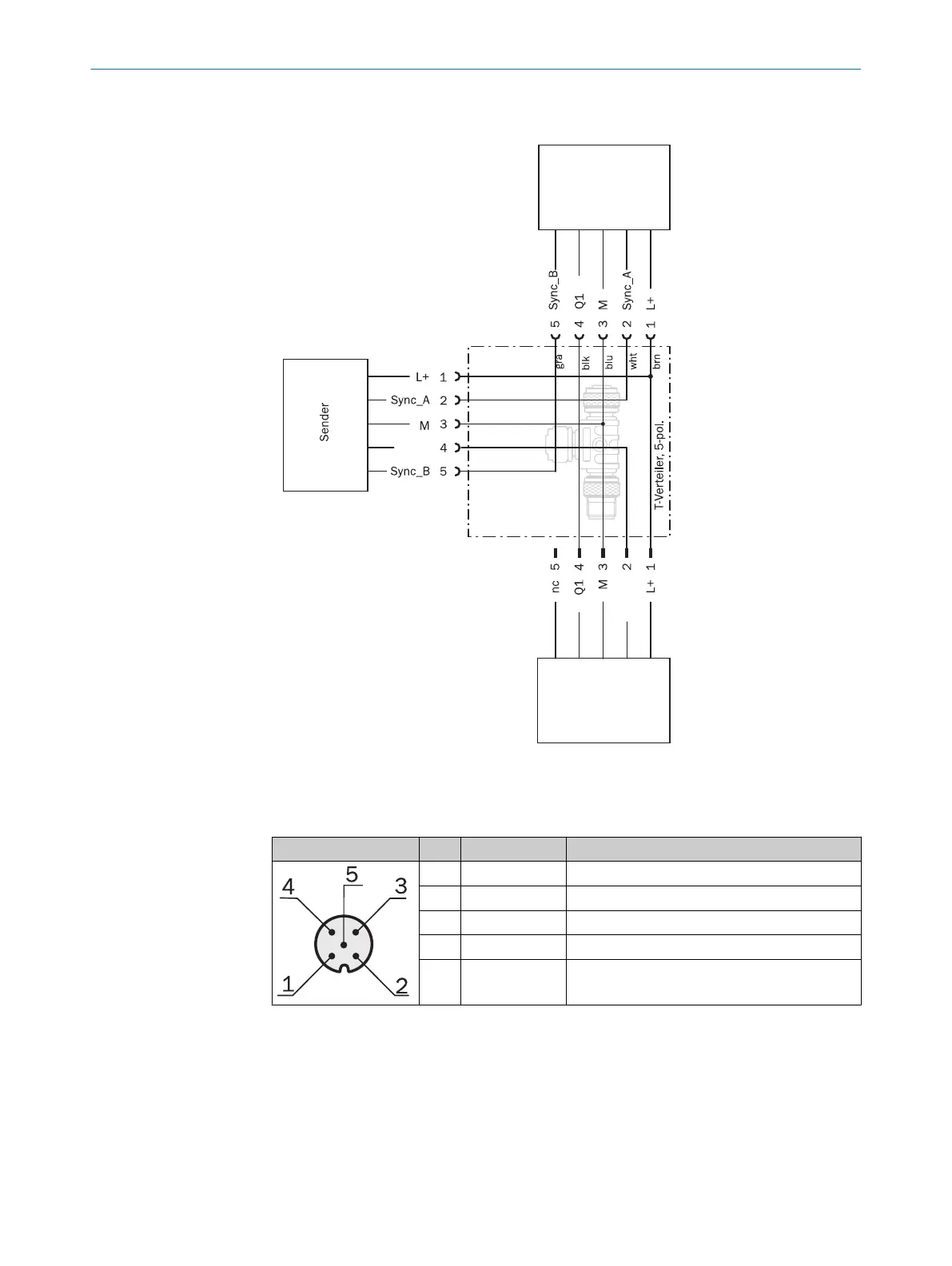
Connection of sender and fieldbus module
Test_In
Feldbusmodul
I/O
Test_In
Figure 38: T-connector for sender and fieldbus module
Table 23
: Pin assignment, I/O connection of the T-connector
Male connector Pin Signal Meaning
1 L+ 24 V supply voltage
2 Test_In Test input
3 M GND supply voltage
4 Q1 Switching output 1
5 Not connected Not assigned (spare)
6 ELECTRICAL INSTALLATION
46
O P E R A T I N G I N S T R U C T I O N S | MLG-2 WebChecker 8025190/2020-01-13 | SICK
Subject to change without notice