MODULARIS Uro Plus SPL1-130.840.02 Page 2 of 34 Siemens AG
Rev. 03 04.05 CS PS 24 Medical Solutions
4 - 2 LITHOSTAR MODULARIS
Shock wave head 4
Shock wave head covers 4
• Switch the system off. Remove the covers on the system unit by removing the screws.
• Remove the water reserve tank and drain the remaining water.
• Reinstall the water reserve tank.
• Switch the system on. Position the support arm in the horizontal position.
• Set service switch S2 on board D3 to position 2 (service on).
• Select "service" on the control unit and then "coupling circuit".
• Activate the corresponding key for "empty" (S6) on the control unit until the coupling
bellow is located next to the lens.
• Switch the system off.
• Only the equipment with ultrasound localization:
- Unscrew the two placement parts for the ultrasound.
- Ensure that the screw lengths are correct when tightening them.
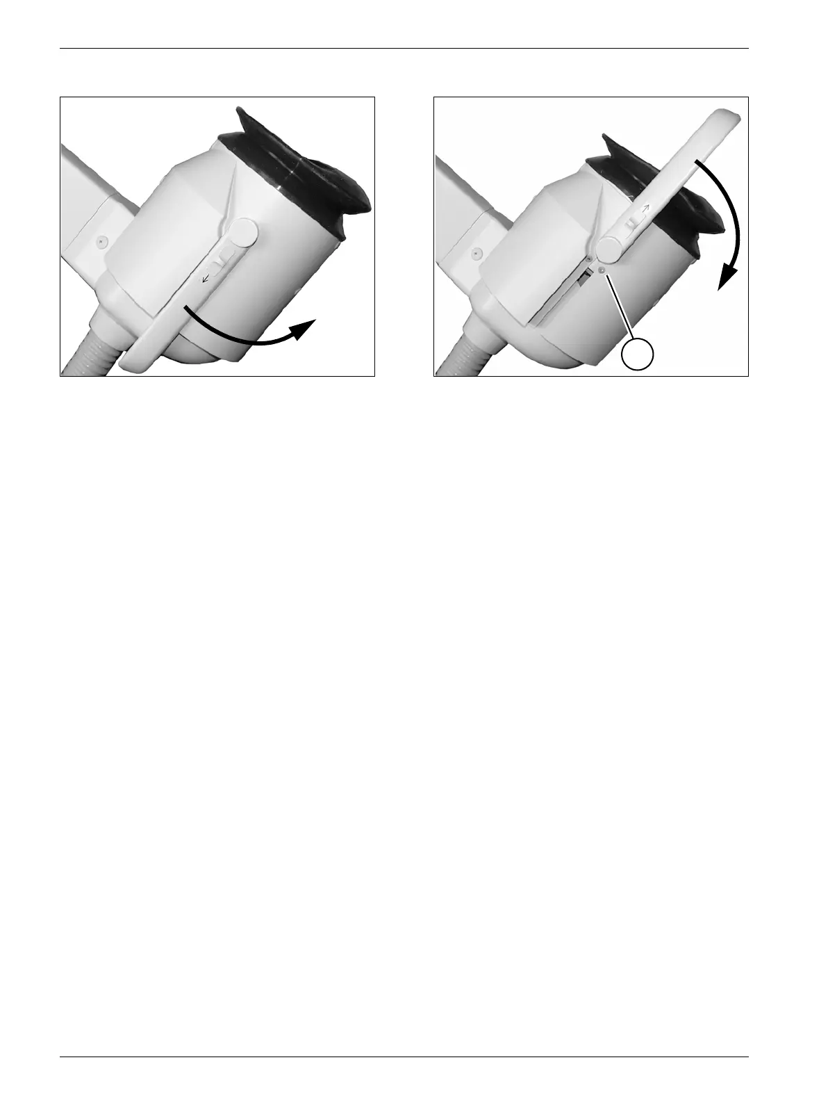
• Remove the mounting screws (I/Fig. 2) for the upper cover on both sides of the shock
head.
• Push the buttons in the direction of the arrow on both sides of the iso-center phantom
(Fig. 2) and at the same time flip the iso-center phantom back (Fig. 1).
• Detach the upper cover, removing it toward the front.
• Push the buttons on both sides of the iso-center phantom in the direction of the arrow
(Fig. 1) and at the same time flip the iso-center phantom up (Fig. 2).
• If required, remove the 3 cover screws from both lower covers and remove the covers.
• Reattach the covers in the reverse order after completion of all work.
Fig. 1 Fig. 2
I