LITHOSTAR MODULARIS 4 - 15
Siemens AG SPL1-130.840.02 Page 15 of 34 MODULARIS Uro Plus
Medical Solutions Rev. 03 04.05 CS PS 24
High voltage connector 4
• Remove the covers of the basic system unit and the shock wave head.
• Remove the shock wave head (refer to the corresponding section).
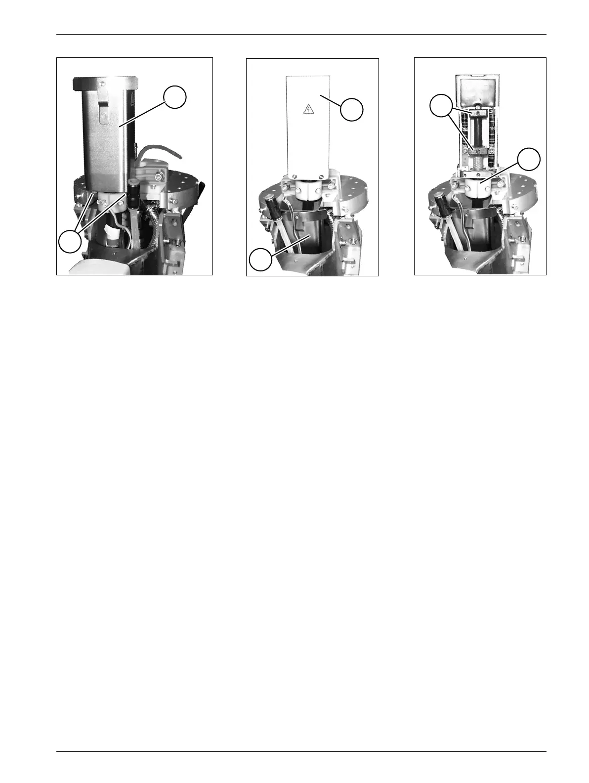
• Remove the cover at the charging unit above the high-voltage connection by removing
the screws (Fig. 13).
• Remove the three clamps (N/Fig. 13) on the high-voltage connection.
• Push the high voltage cable (HK/Fig. 16) in the direction of the shock wave head through
the corrugated tubing until the high-voltage connector is accessible (Fig. 15).
• Remove the screws (S/Fig. 15) on the high voltage connector.
• Push the metal housing (G/Fig. 16) above the high-voltage plug toward the back.
• Open the cover (D/Fig. 16) of the high-voltage connector.
• Remove the connection clamps (M/Fig. 17) in the old high-voltage connector.
• Open the cable clamps (KS/Fig. 17) of the high-voltage connector.
• Connect the new high-voltage connector; reconnect and secure it in the reverse order of
the removal.
• Push the high-voltage cable back in the direction of the charging unit (in the basic unit)
and connect it (Fig. 13).
• Mount the shock wave head assembly (refer to the corresponding section).
• Attach all covers (refer to the corresponding sections).
Fig. 15 Fig. 16 Fig. 17
G
S
G
D
M
KS