LITHOSTAR MODULARIS 4 - 5
Siemens AG SPL1-130.840.02 Page 5 of 34 MODULARIS Uro Plus
Medical Solutions Rev. 03 04.05 CS PS 24
Installing the shock wave head 4
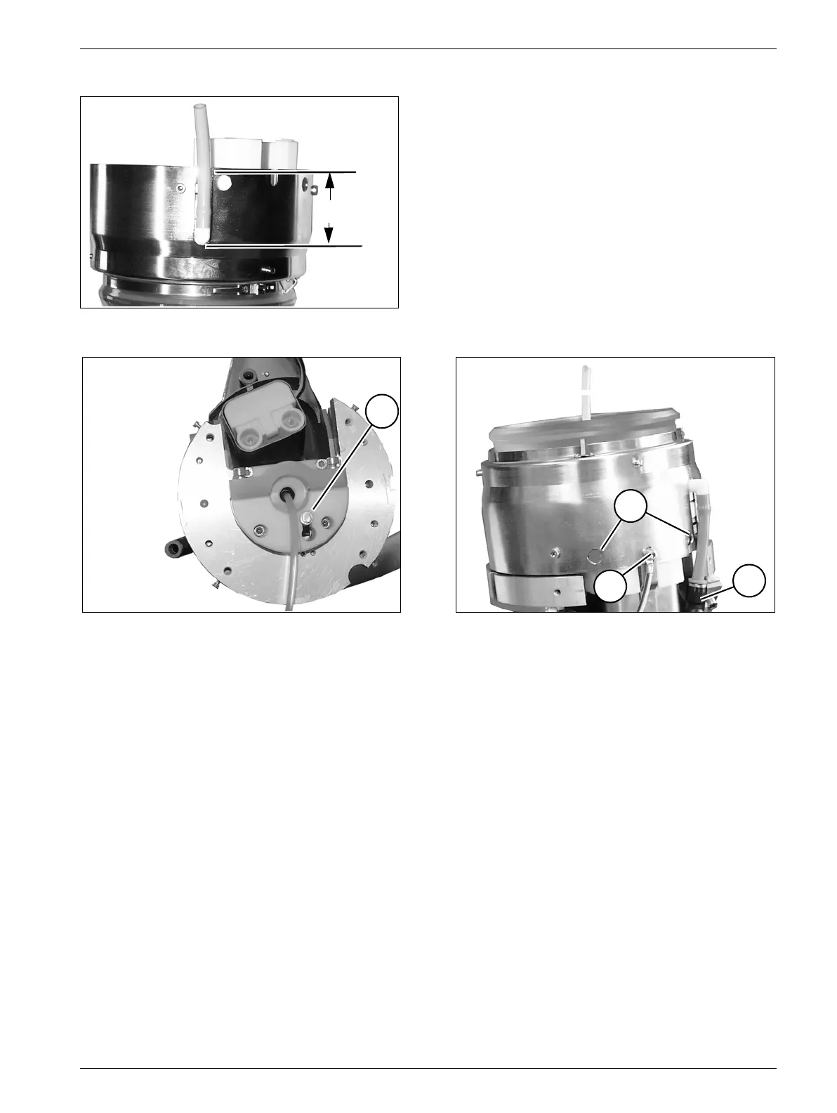
• Shorten both hoses at the shock wave head corresponding to the dimensions in Fig. 5.
• Check that the spring-mounted temperature sensor (T/Fig. 6) is seated correctly in the
groove.
• Insert the air suction hose centrally through the shock wave head (L/Fig. 9).
• Install the new shock wave head from above and insert the water hoses;
when doing this ensure that the hose marked in red (R/Fig. 7) is located next to the
high-voltage connector and that the air suction hose underneath the shock wave
head is neither kinked nor caught in the shock wave head.
• Attach the shock wave head with the Allen screws (O/Fig. 7) visible through the opening.
• Push the high-voltage plug as far up as possible, until the openings (O/Fig. 7) are
covered again.
• Reattach the screw (SL/Fig. 7) with the protective conductor.
• Retighten the 2 Allen screws (U/Fig. 4) underneath the shock wave head.
• Place the iso-center phantom on top so that it is flush and secure it with the four screws
(V/Fig. 3) (use an Allen key with a guide pin for this purpose).
Fig. 5
Fig. 6 Fig. 7
48 ±1 mm
SL
R
O
T