Iso-center with X-Ray 5 - 7
Siemens AG SPL1-130.840.02 Page 7 of 8 MODULARIS Uro Plus
Medical Solutions Rev. 03 04.05 CS PS 24
Adjusting the 20° position
• Move the C-arm into one of the two 20° positions.
• Switch FL ON briefly.
The ball must be in the center of the cross (refer to Fig. 8), if not:
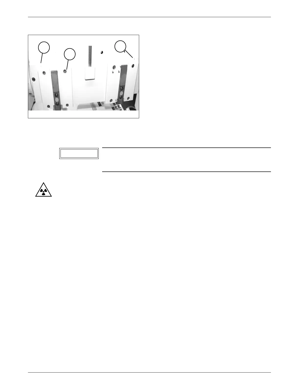
- decouple the LITHOSTAR MODULARIS from the SIREMOBIL Iso-C and slightly
loosen the eight screws (1/Fig. 10).
- Recouple the LITHOSTAR MODULARIS to the SIREMOBIL Iso-C.
- Move the C-arm into the 20° position.
- Use the adjustment screws (2/Fig. 10) to adjust the support arm so that the ball is
located in the cross-hairs (refer to Fig. 8).
- Once the iso-center is correctly set, couple the LITHOSTAR MODULARIS again and
tighten the eight screws (1/Fig. 10) with a torque of 10 Nm.
- Recouple the LITHOSTAR MODULARIS to the SIREMOBIL Iso-C and check the
switch setting on the SIREMOBIL Iso-C for column stop and reset if necessary.
- Angulation motor - check adjustment.
Concluding work 5
• Perform the protective conductor measurement.
• Perform a function check.
Fig. 10
The position of the ball must not be identical in both 20° positi-
ons. The tolerances must however be maintained, refer to
Figure 8.
1
2
2
NOTICE