Iso-center with X-Ray 5 - 5
Siemens AG SPL1-130.840.02 Page 5 of 8 MODULARIS Uro Plus
Medical Solutions Rev. 03 04.05 CS PS 24
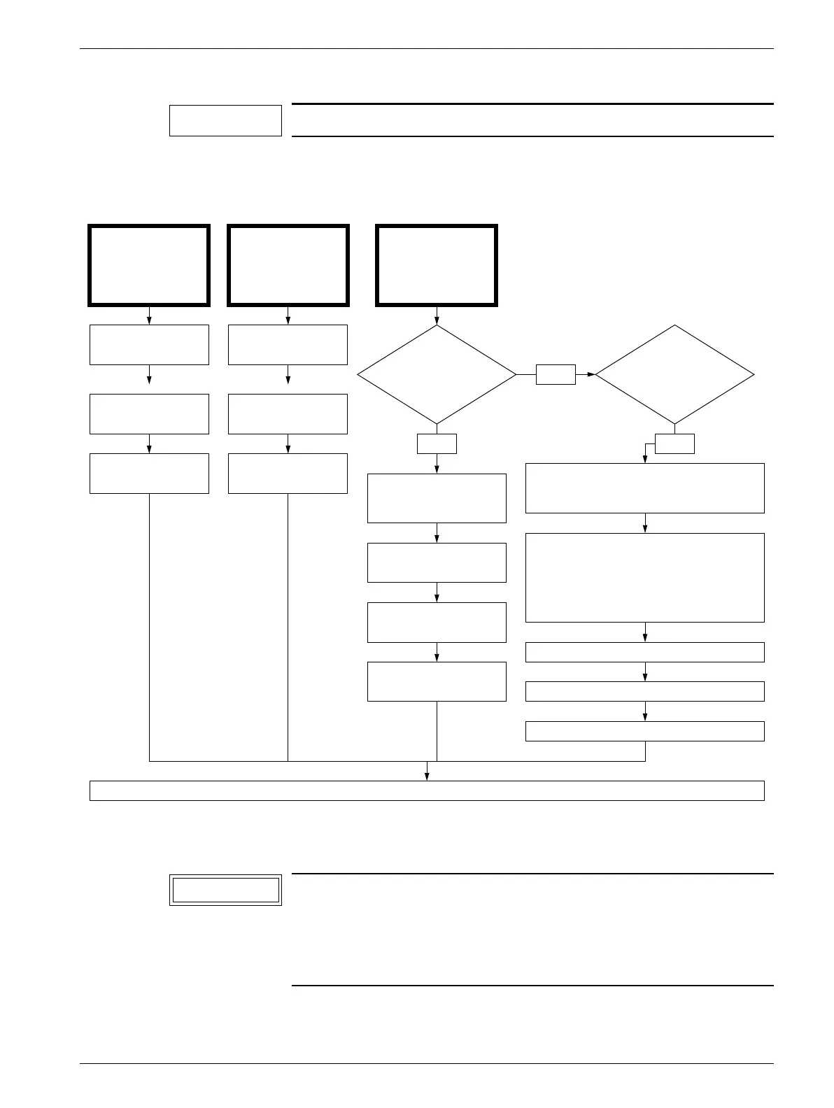
LITHOSTAR MODULARIS from support arm serial number 0051
Adjustment procedure 5
Prerequisite: The potentiometer must be correctly adjusted on the motor.
If screws were loosened on the adjustment direction of the shock wave head they must be
tightened before checking the iso-center with X-ray.
The ball will jump when zooming, but this has no effect.
Before the iso-center can be checked or adjusted, the following
settings must be performed on the SIREMOBIL Iso-C:
1. Camera rotation to 0°.
2. Deselect image reverse vertical (LED is off).
3. Deselect image reverse horizontal (LED off).
NOTE
I.I. replacement
X-ray tube /
collimator repla-
cement
Shock wave
head
replacement
Iso-center adjustment
0° position
Iso-center adjustment
-20° position
Iso-center adjustment
+20° position
Iso-center adjustment
0° position
Iso-center adjustment
-20° position
Iso-center adjustment
+20° position
1 LITHOSTAR
MODULARIS and several
SIREMOBIL
Iso-C
1 LITHOSTAR
MODULARIS and
1 SIREMOBIL Iso-C
No
Yes
Set iso-center the same as
with support arm from serial
number 0051
Yes
Check the iso-center; the setting must be identi-
cal to that of the defective shock wave head. To
avoid having to readjust the iso-center on all
SIREMOBILES, perform the same check as
with support arm to serial number 0050
Prior to replacing the shock wave head, view the
iso-center (the three positions) and either save it
or make a hardcopy.
Iso-center adjustment
0° position
Iso-center adjustment
-20° position
Iso-center adjustment
+20° position
Iso-center adjustment 0° position
Iso-center adjustment -20° position
Iso-center adjustment +20° position
Concluding work
NOTICE