MODULARIS Uro Plus SPL1-130.840.02 Page 26 of 34 Siemens AG
Rev. 03 04.05 CS PS 24 Medical Solutions
4 - 26 LITHOSTAR MODULARIS
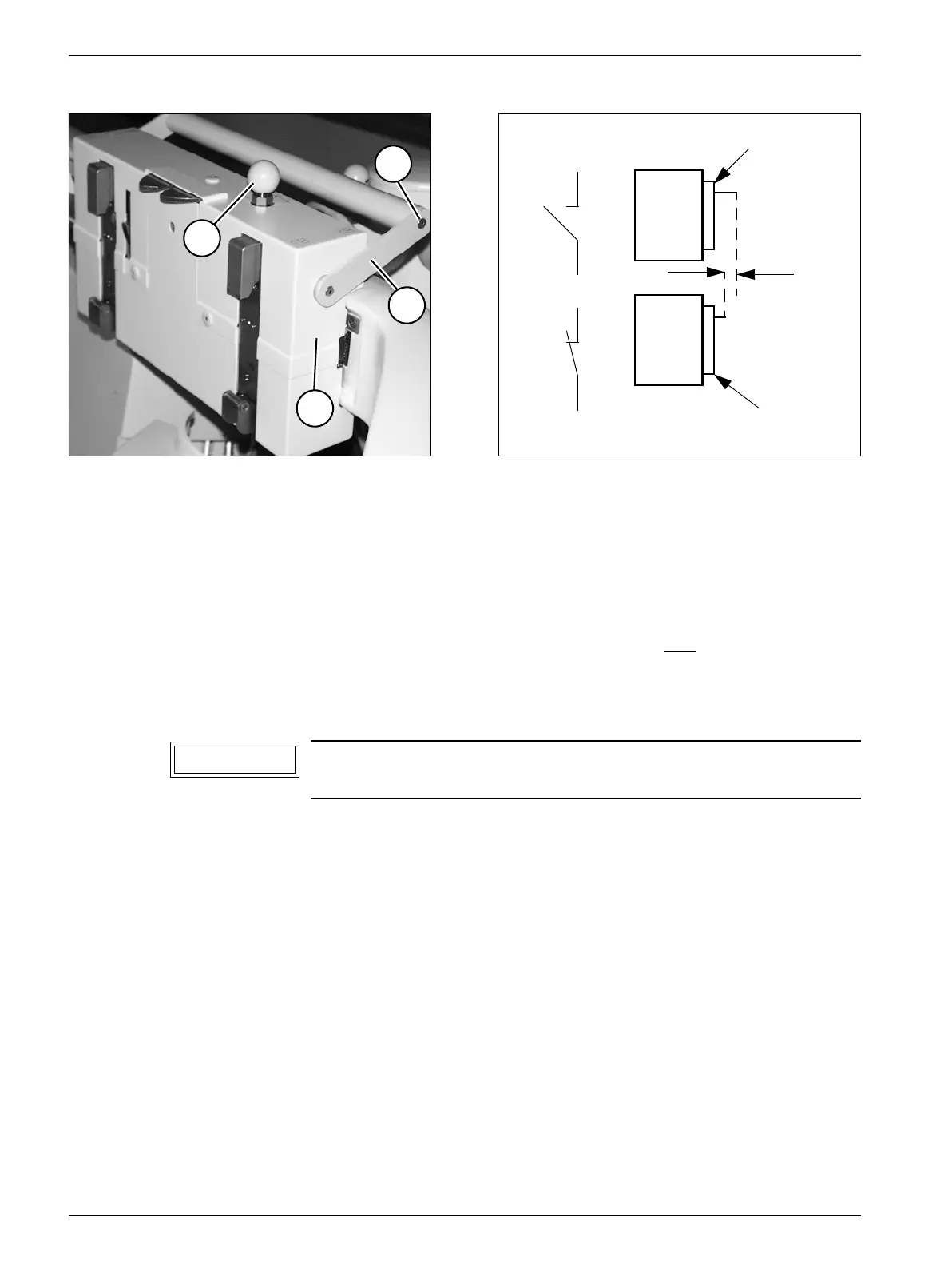
Adjusting switches S1/S2 4
• Adjustment of activating lever (Fig. 31).
• When activating pin S1 (Fig. 29), the travel movement of the vertical column is blocked.
- When activating pin S2 (Fig. 29), both movement directions of the vertical column are
blocked.
• The screws behind the opening (7/Fig. 29) should be loosened only. Move switch until
switching function is activated and tighten screws.
Setting the cam on the LITHOSTAR MODULARIS 4
• Remove the knob (8/Fig. 30); lift up the ball and secure the axis from shifting.
• To support arm serial number 0050
- Remove the countersunk screw (9/Fig. 30).
- Remove all screws from the covers.
- Firmly pull the handle apart (10/Fig. 30).
Fig. 30 Fig. 31
Only necessary if the switch on the SIREMOBIL Iso-C cannot be
adjusted.
1 to 0.5 mm
S1/S2
S1/S2
Iso-C
Iso-C
Docking plate
Docking plate
8
9
10
11
NOTICE