Iso-center with X-Ray 5 - 3
Siemens AG SPL1-130.840.02 Page 3 of 8 MODULARIS Uro Plus
Medical Solutions Rev. 03 04.05 CS PS 24
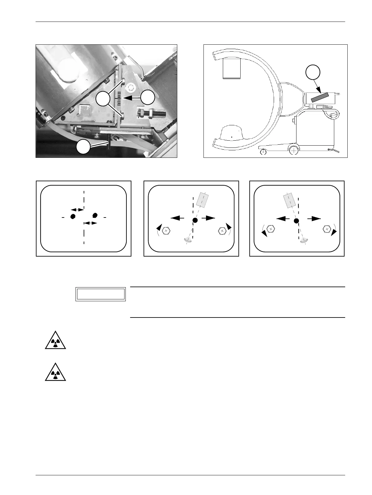
Adjusting the 20° position 5
• Move the C-arm into one of the two 20° positions.
• Switch FL ON briefly.
The ball must be in the center of the cross (refer to Fig. 1).
• Move the C-arm into the other 20° position.
• Switch FL ON briefly.
The ball on the adjustment area must be located in the center of the centering cross
(refer to Fig. 1).
• The distance from the phantom to the center of the centering cross must be the same for
both 20° positions (with a maximum deviation of ± 2 mm) (refer to C/Fig. 6).
Fig. 4 Fig. 5
Fig. 6
The position of the ball must not be identical in both 20° positi-
ons. The tolerances must however be maintained, refer to
Figure 1.
8
5
6
7
E
RBV
with 6/Fig.4
D
with 6/Fig.4
RBV
C
NOTICE