MODULARIS Uro Plus SPL1-130.840.02 Page 18 of 34 Siemens AG
Rev. 03 04.05 CS PS 24 Medical Solutions
4 - 18 LITHOSTAR MODULARIS
Air suction hose 4
To support arm serial number 0050 4
• Remove the covers of the basic system unit and the shock wave head.
• Remove the shock wave head (refer to the corresponding section).
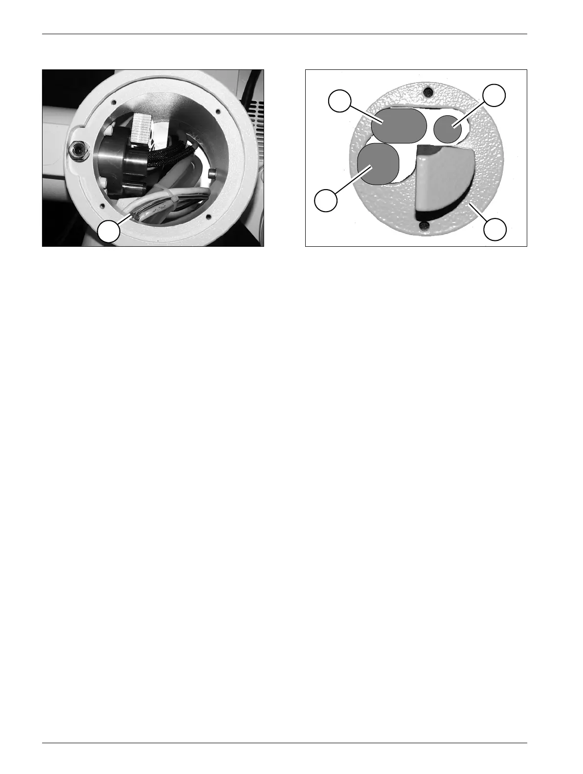
• Pull the temperature sensor (T/Fig. 18) in the shock wave head support somewhat
forward and then push it back through to the side.
• Secure the spiral spring to the sensor supply cable (x/Fig. 19) approx. 4 cm behind the
temperature sensor with adhesive tape (KB/Fig. 19) to keep it from slipping back.
• Remove the white teflon plate (Tp/Fig. 18) by removing the screws.
• Push the high-voltage connector (W/Fig. 20) slightly to the side for better access to the
water supply (Fig. 20).
• Now pull the water supply (W/Fig. 20) with the center air suction hose slightly forward in
the shock wave head support and then push it back through to the side.
• Remove the front bracket connection (F/Fig. 25) on the water supply by removing the
screws.
• Remove the front part (E/Fig. 25) of the water supply by removing the screws.
• Disconnect the old water hose.
• Install the new water hose and secure it with the appropriate hardware.
• Remove the front part (E/Fig. 25) of the water supply by removing the screws.
• Puncture the tubing with a needle (app. 1 mm) twice at this point (<-/Fig. 25).
• Insulate the bracket connection of the water supply (F/Fig. 25) just removed, i.e. attach
new teflon insulation tape with the screws; when doing this do not block the opening to
the pressure sensor.
Fig. 23 Fig. 24
6
5
4
3
2