LITHOSTAR MODULARIS 4 - 17
Siemens AG SPL1-130.840.02 Page 17 of 34 MODULARIS Uro Plus
Medical Solutions Rev. 03 04.05 CS PS 24
• To support arm serial number 0050
- Place the water supply (W/Fig. 20) in the shock wave head in the same manner it was
done during deinstallation.
- Reattach the white teflon plate (Tp/Fig. 18).
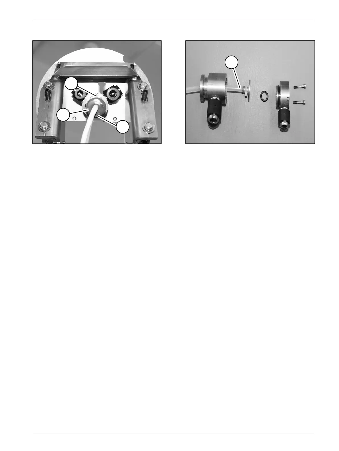
• From support arm serial number 0051
- Reattach the lower part (2/Fig. 21).
- Tighten the two screws (1/Fig. 21).
• Place the temperature sensor (T/Fig. 18) with the spiral spring from the back in the shock
wave head in the same manner it was done during deinstallation; ensure that the spiral
force of the spring pushes the temperature sensor to the front (Fig. 18).
• Reattach the disk (3/Fig. 24) to the corrugated tubing, make sure the leads are correctly
attached.
- High voltage cable (4/Fig. 24)
- Tubing sections (5/Fig. 24)
- Other lead (6/Fig. 24).
• Reattach the corrugated tubing with the screws.
• Route the cables and the hoses according to Fig. 24.
• Reattach the column cover.
• Mount the shock wave head assembly (refer to the corresponding section).
• Reattach all covers (refer to the corresponding section).
Fig. 21 Fig. 22
1
1
1
2