MODULARIS Uro Plus SPL1-130.840.02 Page 6 of 34 Siemens AG
Rev. 03 04.05 CS PS 24 Medical Solutions
4 - 6 LITHOSTAR MODULARIS
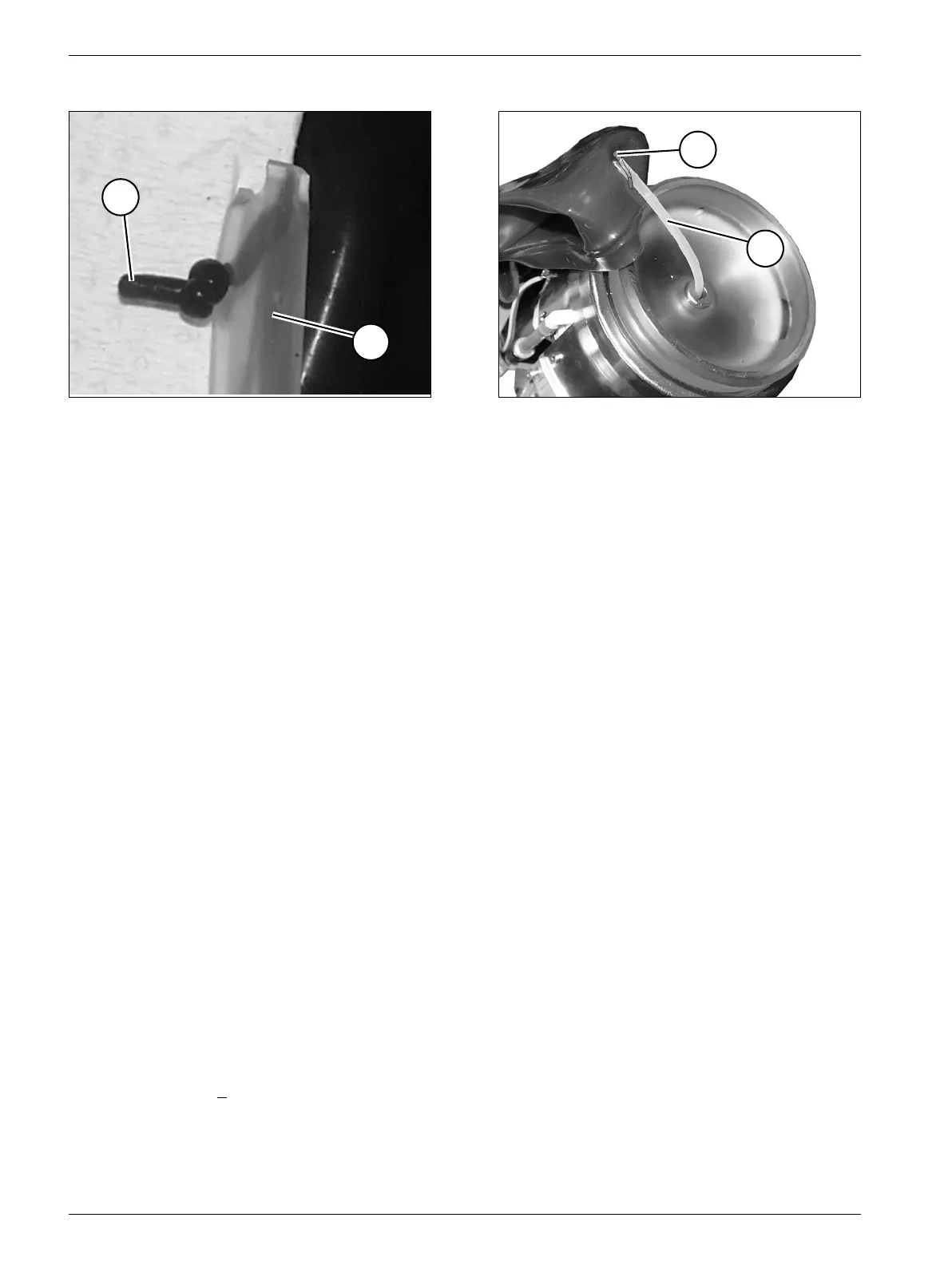
• Insert the air suction hose (L) as shown in Fig. 8 and Fig. 9 carefully over the pin (ST) in
the coupling bellows. Tie a knot to secure it (Fig. 8).
• Install the coupling bellows; when doing this, ensure that the pin (ST/Fig. 9) for
attachment of the hose is positioned at the highest point and is seated correctly in the
clamp.
• Replace the hose pump head for cooling pump M1 (refer to the section "Hose pump
head in the coupling circuit"). (Not necessary if IWAKI pump installed).
• Fill the cooling circuit (refer to the section "Filling the cooling circuit").
• Fill the coupling circuit (refer to the section "Filling the coupling circuit").
• Check the iso-center as described in chapter 5.
• Select "service" and then "coupling circuit" on the control unit.
• Activate the corresponding key for "empty" (S6) on the control unit until the coupling
bellows is located next to the lens.
• Reinstall the covers of the shock wave head according to the procedure for removal.
• Adjust service switch S2 on board D3 to position 1 (service off).
• Select "rinse" on the control unit and activate the cycle (ends automatically).
• Read out the counter for the shock wave head and record the value in the operating
protocol (in Register 4).
• Reset the counter (refer to chapter 3).
• Connect the service PC to the board as described in chapter 3.
• Read out both temperature values on the service PC; the difference must not exceed a
maximum of 3° C.
• Release shock waves: both temperature values should increase closely in parallel
(∆Τ <
3° C).
• Reattach the system cover.
• Perform a function test.
Fig. 8 Fig. 9
L
ST
L
ST