LITHOSTAR MODULARIS 4 - 31
Siemens AG SPL1-130.840.02 Page 31 of 34 MODULARIS Uro Plus
Medical Solutions Rev. 03 04.05 CS PS 24
• Check and correct if necessary the cable run in all positions of the support arm.
• Plug in or fasten cables and hoses again according to designation.
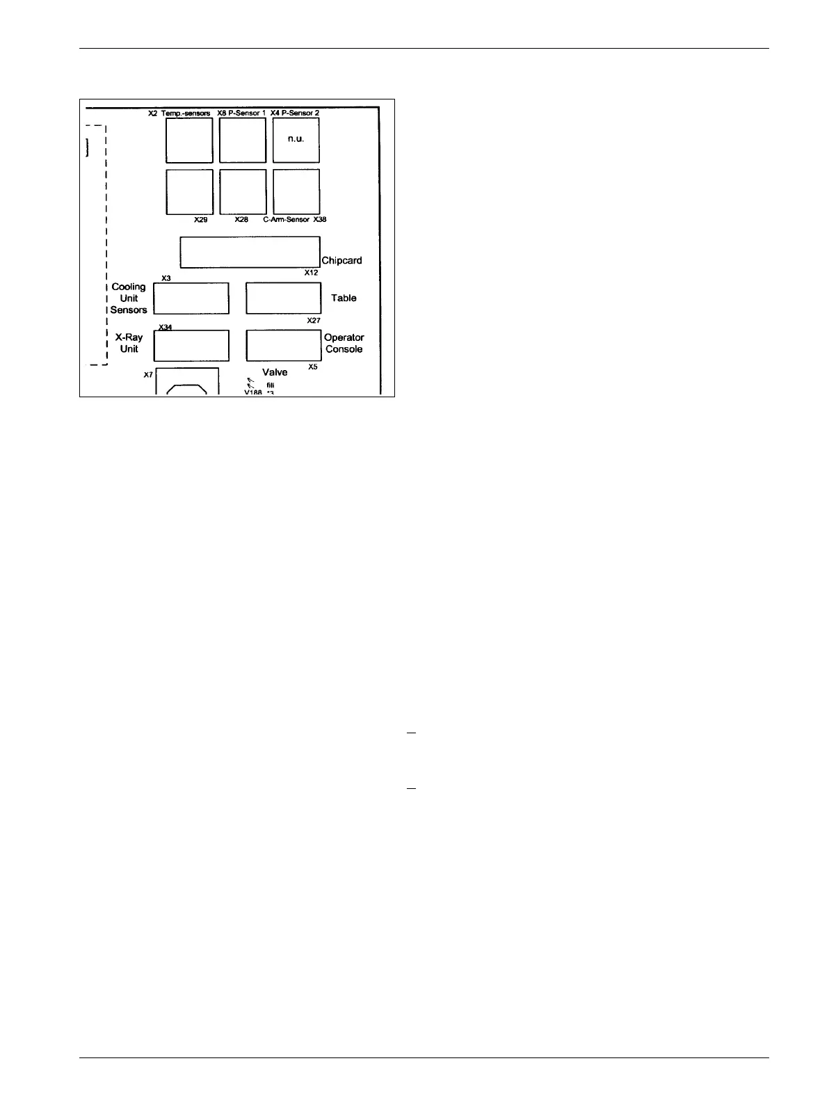
Refer to Fig. 38 for plug designations on board D3.
• Install the water supply delivered with the support arm (refer to page 4-18).
• Install the shock wave head completely (refer to page 4-5).
• If the ECG triggering option is available, draw the trigger cable and cable for Sirecust
power supply upwards through the rotary joint.
• Strain-relieve the cable on the docking station and install docking station.
• Fill cooling circuit and coupling circuit (refer to page 4-9).
• Adjustment of the lift switch-off (see page 4-26 (Fig. 30/31)).
• Adjustment of the clamping
- For docking plate serial number <
0050
Turn in the screws (see page 4-27 (17/Fig. 33)) on both clamping hooks symmetrically
until the correct clamping force is reached. Then lock the screws again.
- For docking plate serial number > 0051
(see Installation and Setting Instructions SPL 1-130.033.01 page 4-2).
• Adjustment of the angulation motor (see page 4-23).
• Check shot triggering and centering.
• Attach all cover parts.
Fig. 38
12