Service selector switch
Data are backed up using a service selector switch as follows:
1.
Set the service selector switch to "Diagnostics" (i.e. set DIP switch S7 to ON).
The switch positions of the mode switches are not relevant (i.e. the operating mode set
remains unchanged).
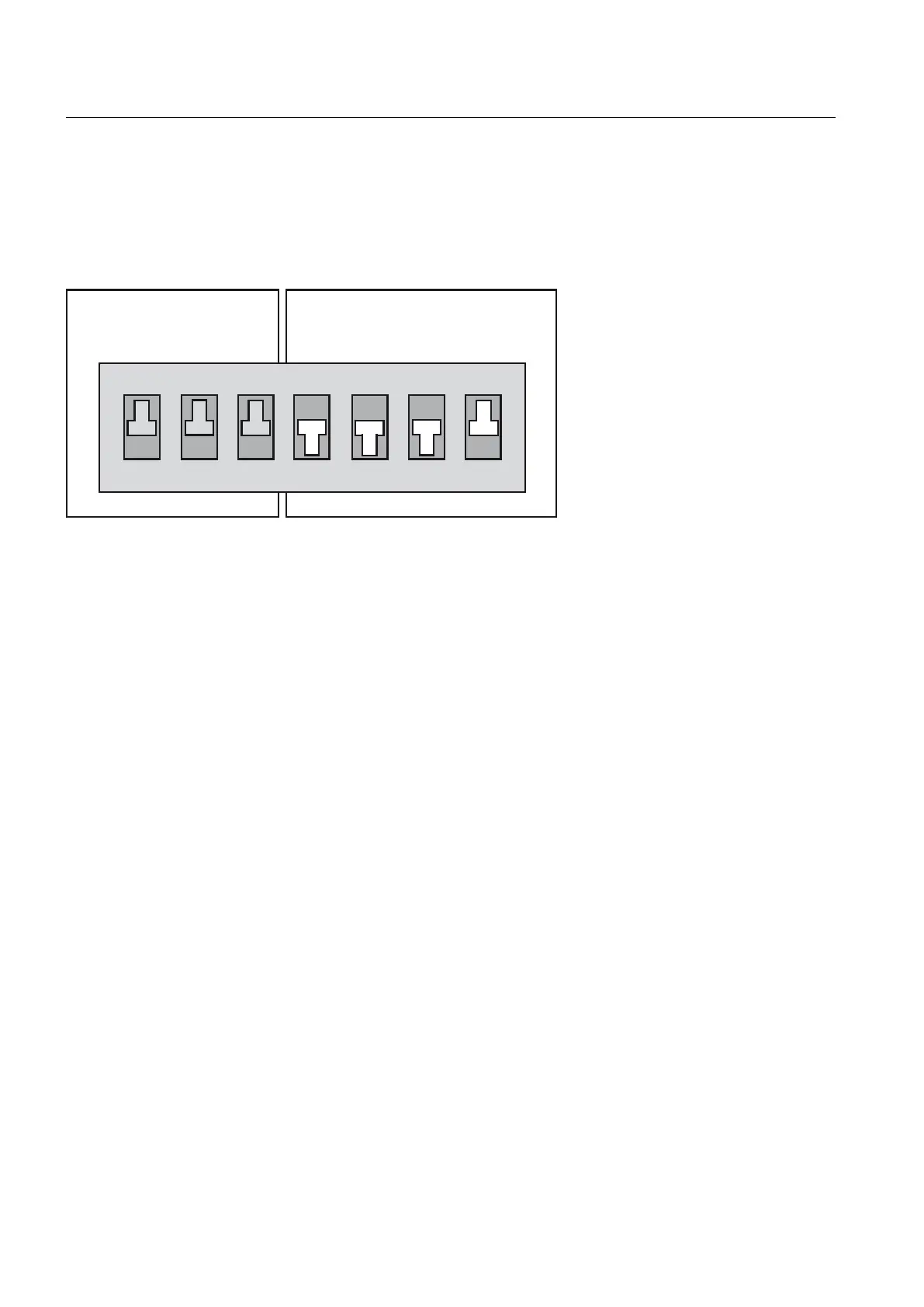
6ZLWFKVHWWLQJ 21
6ZLWFKVHWWLQJ 2))
0RGHVHOHFWRUVZLWFK
6WR6
6HUYLFHVHOHFWRUVZLWFK
6WR6
2
1
Figure 7-3 Writing diagnostic data using a switch position
2.
Switch the SIMOTION D410 off and on again.
3. Wait for the device to start up.
The diagnostic data and non-volatile SIMOTION data are backed up to the CF card during
power-up, provided that this is still possible and is not prevented by hardware defects,
for example. The status LEDs indicate the backup process on the SIMOTION D410 as
follows:
– Backup in progress: RUN/STOP LED flickers yellow
– Backup complete: RUN/STOP LED flickers green
4. Once the backup is complete, switch off the D410.
5. Remove the CF card and reset the service selector switch to its original setting.
INI file in the main directory of the CF card
1. Use a text editor (such as Notepad) to create a file called simotion.ini
2. Add the following text: DIAG_FILES=1
You must use a text editor and may not use any formatting in the text.
3. Copy the simotion.ini file to the main directory of the CF card.
4. Insert the CF card into the module, which is switched off.
5. Switch the SIMOTION D410 on and allow the SIMOTION device to start up.
The diagnostic data and non-volatile SIMOTION data are backed up to the data carrier
during startup, provided that this is still possible and is not prevented by HW defects,
for example. The status LEDs indicate the backup process on the SIMOTION D410 as
follows:
– Backup in progress: RUN/STOP LED flickers yellow
– Backup complete: RUN/STOP LED flickers green
Diagnostics data
7.2 Diagnostic data and non-volatile SIMOTION data
SIMOTION D410
206 Commissioning Manual, 04/2014

 Loading...


