326
7DUJHW3RVLWLRQ
U6B$FWB75
75$9(/
75$9(/B):
%5$.(B&/26('
,1
,1
,1
287
,1
,1
287
PP
PP
PPV
U9B326B75
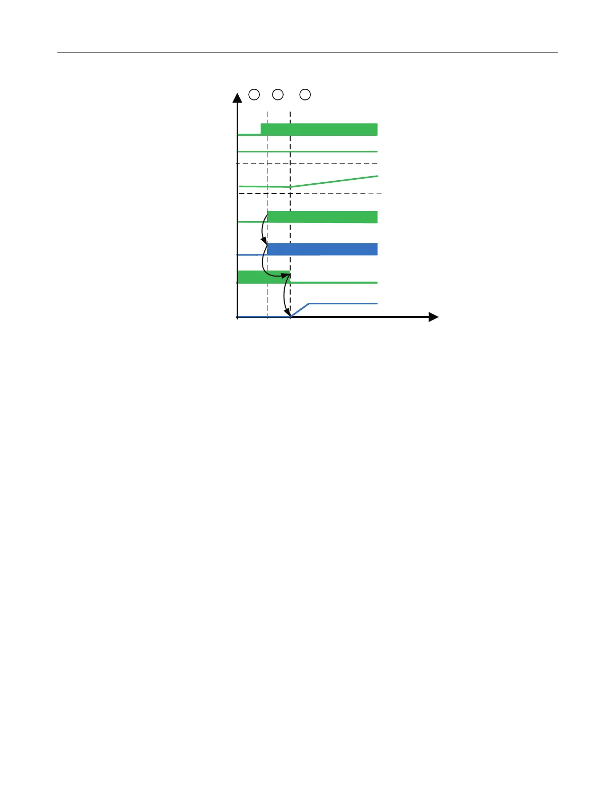
Figure 6-5 Signal sequence at the start of travel in positioning mode (trolley)
Section 1:
The sway control system is activated and positioning mode is selected for the drive. A target
position has been specified.
Section 2:
The positioning operation is initiated by setting the TRAVEL control bit. If no error has occurred
that disables the operating mode, direction signals are set, triggering opening of the brake (see
Chapter Drive activation and brake control (Page 163)).
Section 3:
The brake is opened. The output velocity "rV_Pos_TR" is transferred to the drive.
End of travel
Travel is complete when the POS_COMPLETED status bit is set:
● The difference between the current and target positions is less than the set positioning
accuracy.
● The SC_COMPLETED status bit is set.
● The output velocity is less than or equal to the zero speed detection.
The following signal sequence is performed:
Sway Control function description
6.2 Sway Control operating modes
SC integrated STS, GSU
Operating Instructions, 07/2019, A5E48271265B AA 153
 Loading...