7.1 Requirements
7.1.1 Mechanical requirements for TLS with a hydraulic system
A defined configuration of mechanical requirements on the crane for implementation of the TLS
function:
● Cylinders (equipped with proportional valves for continuous velocity control)
● Hoist cables
● Spreader suspension
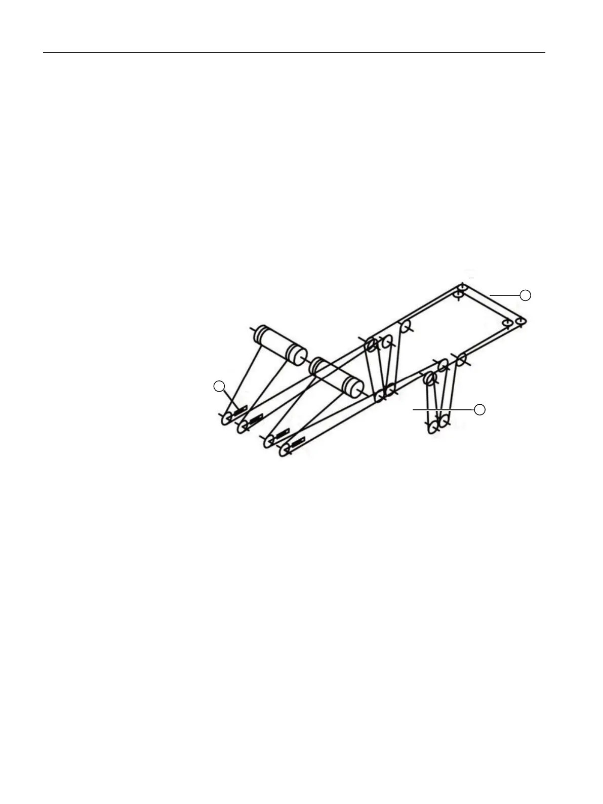
The figure below shows such a configuration by way of example.
① A, B, C, D Hydraulic cylinders
② R1 - R4 Guide rollers
③ P
A
, P
B
, P
C
, P
D
Suspension points
Figure 7-2 Direction of movement of hoist cables with skew drive
The following relationships between cylinder and spreader movements must apply:
● When a cylinder is extended, the associated suspension point on the spreader is raised.
● Trim movement:
Synchronous travel motion of the following cylinders: Extension of cylinders A and B /
retraction of cylinders C and D, or vice versa
● List movement:
Synchronous travel motion of the following cylinders: Extension of cylinders A and D /
retraction of cylinders B and C, or vice versa
● Skew motion:
Synchronous travel motion of the following cylinders: Extension of cylinders A and C /
retraction of cylinders B and D, or vice versa
TLS control function description
7.1 Requirements
SC integrated STS, GSU
238 Operating Instructions, 07/2019, A5E48271265B AA
 Loading...