7.1.2 Mechanical requirements for TLS with a hydraulic system and electric drive
Mechanical requirement on the crane for implementation of the TLS function:
● Defined configuration of
– Cylinders (equipped with proportional valves for continuous velocity control)
– Hoist cables
– Spreader suspension
● An electric drive at the tip of the boom hoist
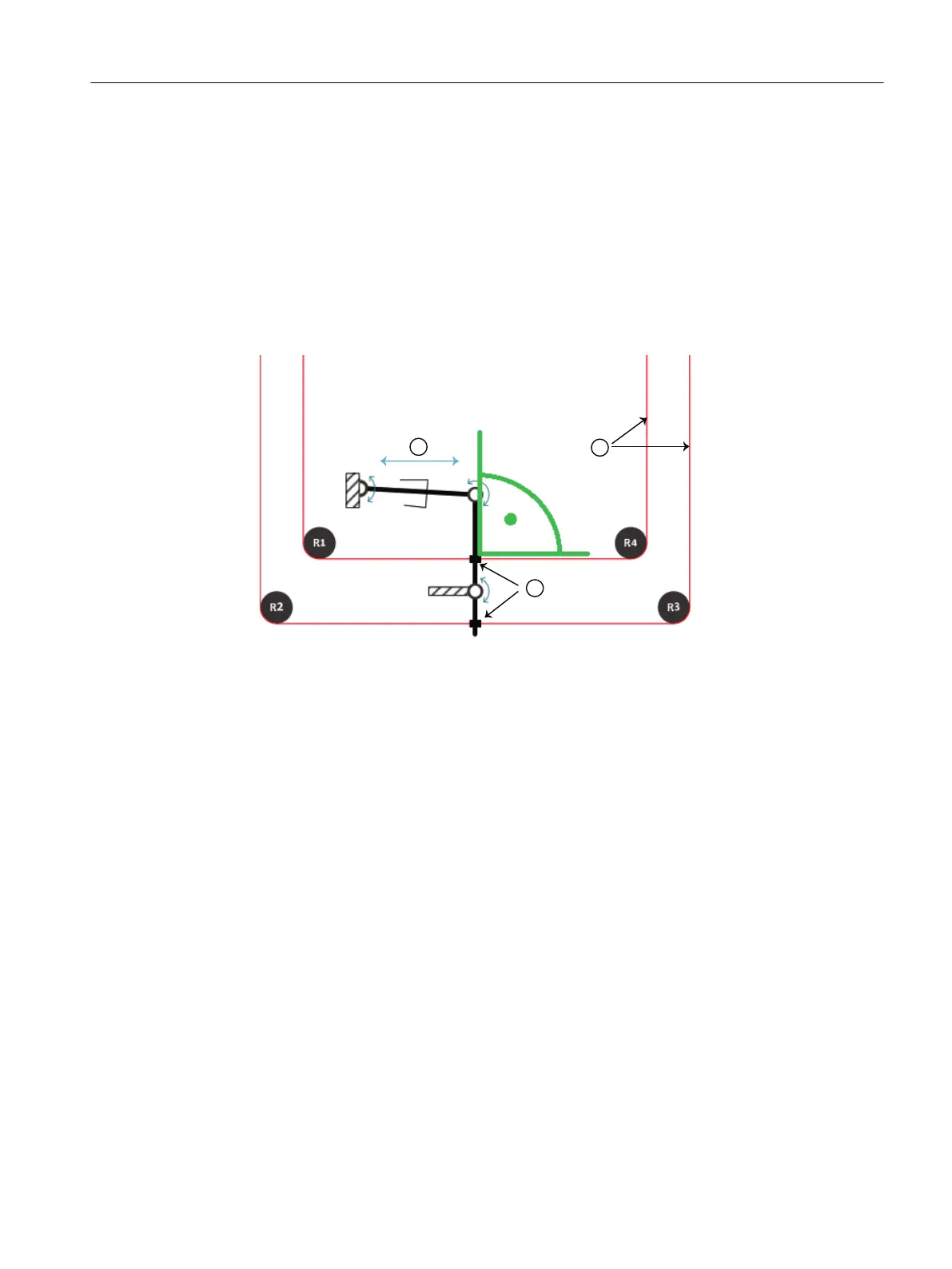
① Electrically driven spindle
② Hoist cables
③ Hoist cable fastening
Figure 7-3 Zero position of the skew drive spindle
The figure above shows a schematic mechanical structure at the tip of the boom hoist. Four
guide pulleys (R1-R4) guide the hoist cables. An electric drive with a spindle is also installed.
The hoist cables ② are pulled in the predefined directions via the fastenings ③ based on the
linear movement of the electrically driven spindle ①. The spreader then rotates clockwise
(skew CW) or counterclockwise (skew CCW). In this way, skew damping can be implemented
by the electric drive.
The cylinder and electric drive interact as follows:
TLS control function description
7.1 Requirements
SC integrated STS, GSU
Operating Instructions, 07/2019, A5E48271265B AA 239
 Loading...