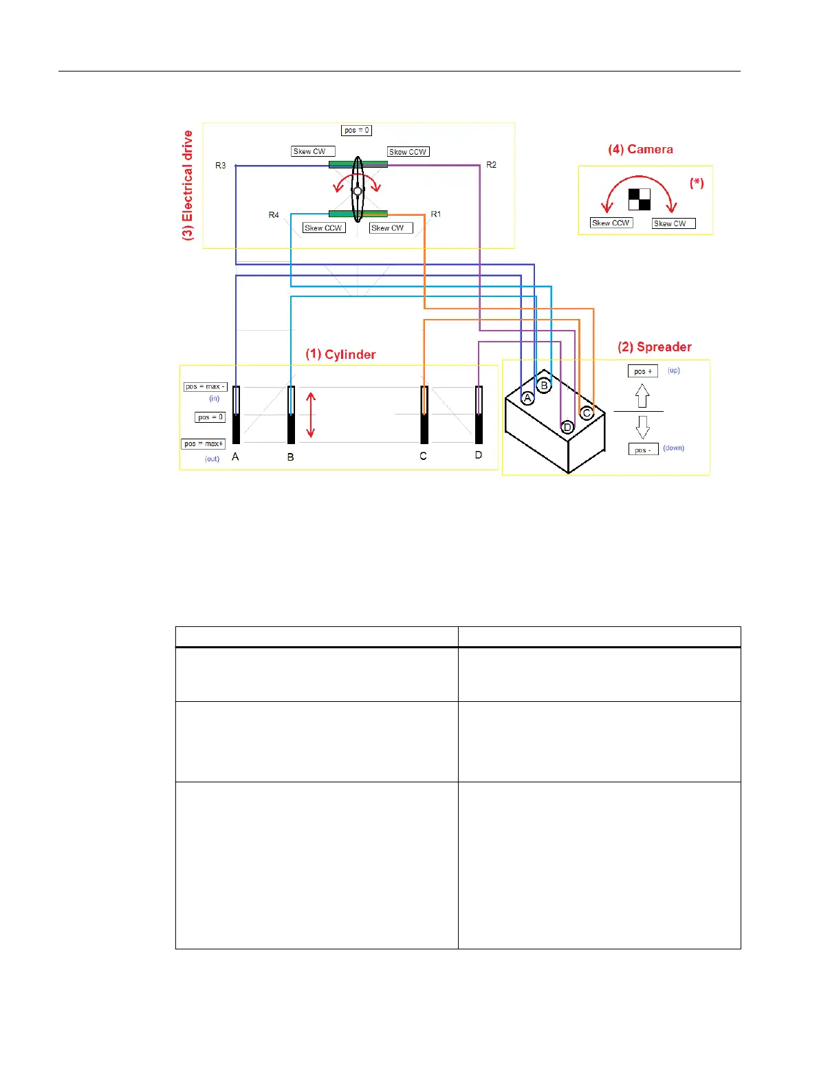
(1) (2) (3) (4) For an explanation, see Table "Directions of movement"
(*) For an explanation, see Table "Directions of movement for skew"
Figure 7-4 Directions of movement
The tables below explain the effects of the directions of movement of the cylinder and the skew
drive on the suspension points.
Table 7-1 Directions of movement
Direction of movement Result
(1) Cylinder
Movement of a cylinder in direction max+
(2) Spreader
Movement of the corresponding suspension point
in direction pos+
(1) Cylinder
Simultaneous movement of
● cylinders A and C in direction max+ and
● cylinders B and D in direction max-
(4) Camera measuring system
Rotary movement in CCW direction is measured
(3) Electric drive
Movement of skew drive in CCW direction
(2) Spreader
Motion
● of suspension points P
A
and P
C
in direction pos
+ (up) and
● of suspension points P
B
and P
D
in direction
pos- (down)
(4) Camera measuring system
These combine to give a rotational movement in
direction CCW
TLS control function description
7.1 Requirements
SC integrated STS, GSU
240 Operating Instructions, 07/2019, A5E48271265B AA
 Loading...