10.03
4.3 Closed-loop velocity control
4-105
Siemens AG, 2003. All rights reserved
SINUMERIK 840D/SIMODRIVE 611 digital, HLA Module (FBHLA) - 10.03 Edition
The velocity setpoint is limited in the positive and negative directions.
Note
The maximum rapid traverse velocity of the drive (G0 function) is determined
by NC machine parameter 32000.
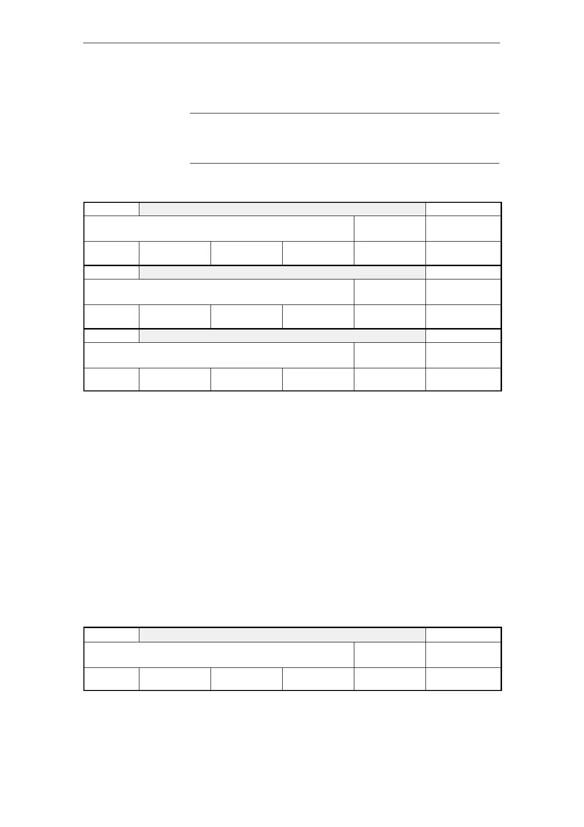
5420 DRIVE_MAX_SPEED_SETUP Cross reference: -
Max. velocity for setup mode
Related to:
HLA
Protection level:
3/3
Unit:
mm/min
Default:
10.0
Minimum:
0.0
Maximum:
120 000.0
Data type:
FLOAT
Active:
Immediately
5440 POS_DRIVE_SPEED_LIMIT Cross reference: -
Positive velocity setpoint limit
Related to:
HLA
Protection level:
3/3
Unit:
mm/min
Default:
0.0
Minimum:
0.0
Maximum:
120 000.0
Data type:
FLOAT
Active:
Immediately
5441 NEG_DRIVE_SPEED_LIMIT Cross reference: -
Negative velocity setpoint limit
Related to:
HLA
Protection level:
3/3
Unit:
mm/min
Default:
0.0
Minimum:
0.0
Maximum:
120000.0
Data type:
FLOAT
Active:
Immediately
With a differential cylinder, the physically possible velocities for piston travel-out
and travel-in are asymmetrical. For this reason, it is advisable to set asymmetri-
cal limitations. A message is sent to the PLC if the limit is violated.
If setup mode is selected, then the velocity setpoint is set to the value in MD
5420 for both directions. The velocity setpoint limitation is calculated as part of
the “Calculate drive model data” operation and
MD 5440 and MD 5441 are preset accordingly.
To protect mechanical components against excessive wear and damage, the
drive acceleration setpoints can be limited by the NC. Linear interpolation of the
velocity setpoints (see MD 5004: CTRL_CONFIG, bit 12; velocity setpoint inter-
polation) ensures that the drive accelerates at the rate specified by the control.
A function for limiting the acceleration in the drive has not been implemented.
(A braking ramp is operative only if the velocity controller is disabled, see MD
5402: SPEED_CTRL_DISABLE_STOPTIME).
The controlled system gain is entered in MD 5435 after “Calculate drive model
data” and should not be altered unless it is incorrect. The value in MD 5435 is
the reference for the P gain of the velocity controller.
5435
CONTROLLED_SYSTEM_GAIN [n] 0...7 index of the parameter set
Cross reference: -
Controlled system gain Related to:
HLA
Protection level:
3/3
Unit:
mm/Vmin
Default:
0.0
Minimum:
0.0
Maximum:
20000.0
Data type:
FLOAT
Active:
Immediately
Velocity setpoint
limitation
Acceleration
limitation
Servo gain
4 Firmware Drive Functions

 Loading...


