10.03
A.2 Cylinder
A-254
Siemens AG, 2003. All rights reserved
SINUMERIK 840D/SIMODRIVE 611 digital, HLA Module (FBHLA) - 10.03 Edition
A.2 Cylinder
The cylinder acts as the drive element in the electro-hydraulic control loop.
It converts the flowrate into rectilinear motion. In this case, high velocities are
required for rapid traverse movements as well as slow velocities for machining
operations
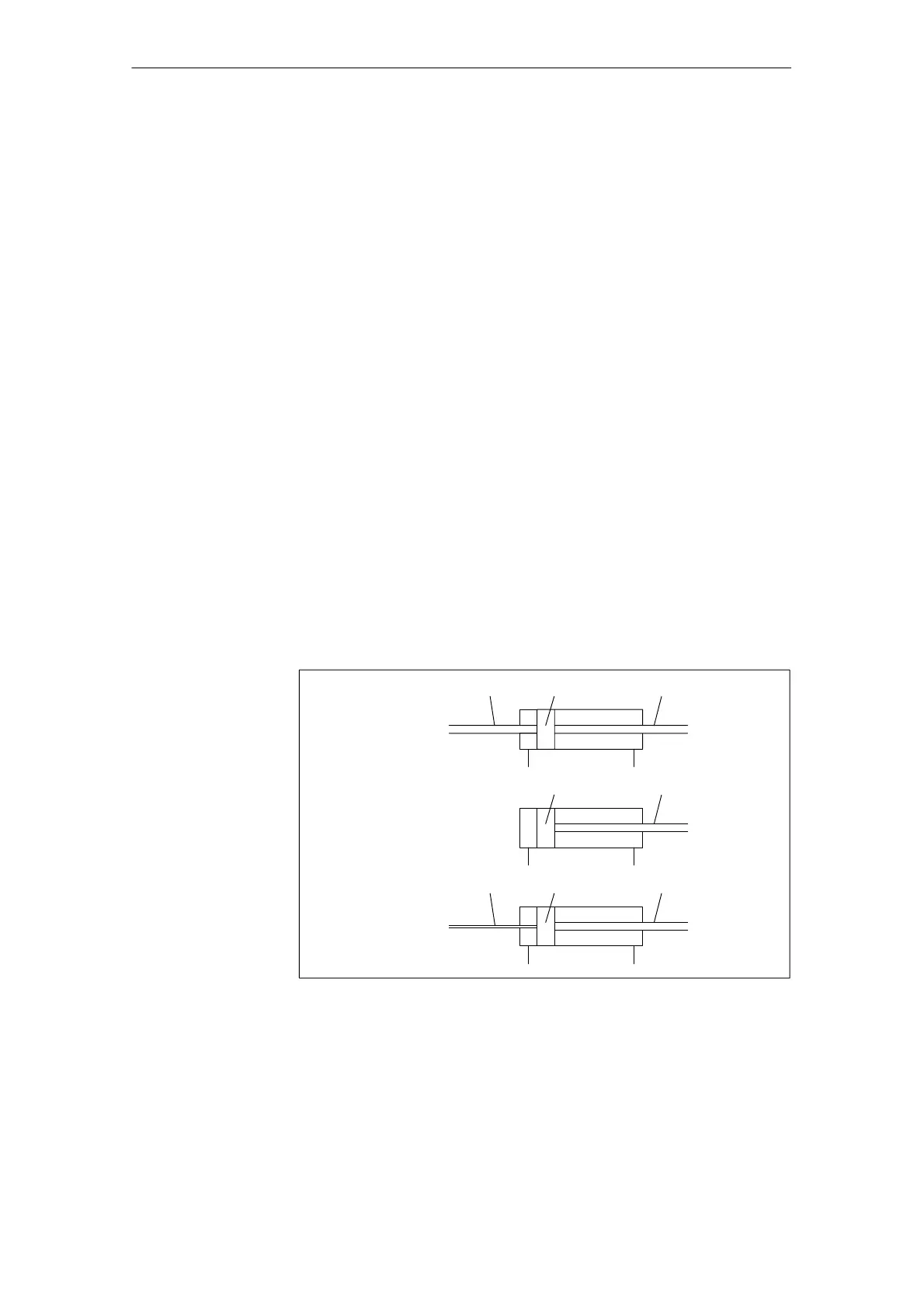
On a through-rod cylinder, a piston rod of the same diameter is mounted at both
ends as a power transmission element. Consequently, the piston areas at the
A and B ends are identical. Likewise, at a constant piston speed, the incoming
flow is equal to the displaced flow in the settled state. The through-rod cylinder
acts symmetrically both when traveling in and when traveling out.
In contrast to the through-rod cylinder, a differential cylinder has either a power-
transmission piston rod at one end only or the piston rods at its two ends have
different diameters. In the latter case, the piston areas at the A and B ends are
different. Furthermore, at a constant piston speed, the displaced flow is not the
same as the incoming flow. The maximum piston travel-in and travel-out speeds
are not the same on a differential cylinder (see Section 4.7).
This asymmetry can, however, be compensated by means of the piston area
adaptation function (MD 5112: VALVE_FLOW_FACTOR_A_B) on the HLA mod-
ule.
Apart from the piston diameter, it is necessary to specify the rod diameters at
the A and B ends. On a differential cylinder, both rod diameters are different,
one of the rods might even have a zero diameter. The maximum piston stroke
and cylinder dead volume are also required.
Differential cylinder
D
0
D
1
OB
Through-rod cylinder
D
2
D
0
D
1
OB
D
1
=D
2
D
2
D
0
D
1
OB
D
1
0D
2
Fig. A-19 Cylinder principle
General
Through-rod or
differential
cylinder

 Loading...


