EasyManuals Logo

Siemens Sinumerik 840D Series Function Manual

Siemens Sinumerik 840D Series
288 pages
To Next Page IconTo Next Page
To Previous Page IconTo Previous Page
Page #92 background imageLoading...
Page #92 background image
10.03
3.14 Configuring an OEM valve list
3-92
Siemens AG, 2003. All rights reserved
SINUMERIK 840D/SIMODRIVE 611 digital, HLA Module (FBHLA) - 10.03 Edition
3.14 Configuring an OEM valve list
OEM users can add their own valves to the valve list by copying file ibhlvlvo.ini
to the “\oem” directory. This list is added as a separate item under the heading
“OEM valves” at the end of the system list (Siemens list).
The syntax of the valve list is identical to that of a Windows INI file. The list may
be created under “Start-up”, “MMC” or “Editor”.
Select C:\OEM, then “New”. Enter the filename ibhlvlvo.ini, followed by “OK”.
This file must have the following structure:
[DATA]
Column1 = Column2, Column3, ... , Column15,
.
.
.
[DATA]
ÁÁÁ
Á
Á
Á
ÁÁÁ
;5106
ÁÁÁ
Á
Á
Á
ÁÁÁ
,
ÁÁ
ÁÁ
ÁÁ
,
ÁÁÁÁ
Á
ÁÁ
Á
ÁÁÁÁ
,
ÁÁÁ
Á
Á
Á
ÁÁÁ
5107,
ÁÁ
ÁÁ
ÁÁ
510
8,
ÁÁÁ
Á
Á
Á
ÁÁÁ
510
9,
ÁÁÁ
Á
Á
Á
ÁÁÁ
511
0,
ÁÁ
ÁÁ
ÁÁ
5111
,
ÁÁÁ
Á
Á
Á
ÁÁÁ
511
2,
ÁÁÁ
Á
Á
Á
ÁÁÁ
5113,
ÁÁÁ
Á
Á
Á
ÁÁÁ
511
4,
ÁÁ
ÁÁ
ÁÁ
511
5,
ÁÁÁ
Á
Á
Á
ÁÁÁ
,
ÁÁÁÁ
Á
ÁÁ
Á
ÁÁÁÁ
,
ÁÁÁ
ÁÁÁ
1001=
ÁÁÁ
ÁÁÁ
OEM,
ÁÁ
ÁÁ
01,
ÁÁÁÁ
ÁÁÁÁ
abc type,
ÁÁÁ
ÁÁÁ
90.1,
ÁÁ
ÁÁ
5,
ÁÁÁ
ÁÁÁ
10,
ÁÁÁ
ÁÁÁ
10,
ÁÁ
ÁÁ
39.8
,
ÁÁÁ
ÁÁÁ
1,
ÁÁÁ
ÁÁÁ
0001B,
ÁÁÁ
ÁÁÁ
35,
ÁÁ
ÁÁ
1.0,
ÁÁÁ
ÁÁÁ
90,
ÁÁÁÁ
ÁÁÁÁ
$T7ƕ40,
ÁÁÁ
Á
Á
Á
ÁÁÁ
1050=
ÁÁÁ
Á
Á
Á
ÁÁÁ
OEM,
ÁÁ
ÁÁ
ÁÁ
02,
ÁÁÁÁ
Á
ÁÁ
Á
ÁÁÁÁ
xyz type,
ÁÁÁ
Á
Á
Á
ÁÁÁ
40.2,
ÁÁ
ÁÁ
ÁÁ
5,
ÁÁÁ
Á
Á
Á
ÁÁÁ
10,
ÁÁÁ
Á
Á
Á
ÁÁÁ
10,
ÁÁ
ÁÁ
ÁÁ
40.1
,
ÁÁÁ
Á
Á
Á
ÁÁÁ
1,
ÁÁÁ
Á
Á
Á
ÁÁÁ
0001B,
ÁÁÁ
Á
Á
Á
ÁÁÁ
35,
ÁÁ
ÁÁ
ÁÁ
1.0,
ÁÁÁ
Á
Á
Á
ÁÁÁ
40,
ÁÁÁÁ
Á
ÁÁ
Á
ÁÁÁÁ
$T7ƕ40,
ÁÁÁ
ÁÁÁ
1051=
ÁÁÁ
ÁÁÁ
OEM,
ÁÁ
ÁÁ
03,
ÁÁÁÁ
ÁÁÁÁ
def type,
ÁÁÁ
ÁÁÁ
8.1,
ÁÁ
ÁÁ
35,
ÁÁÁ
ÁÁÁ
10,
ÁÁÁ
ÁÁÁ
10,
ÁÁ
ÁÁ
10,
ÁÁÁ
ÁÁÁ
1,
ÁÁÁ
ÁÁÁ
0000B,
ÁÁÁ
ÁÁÁ
200,
ÁÁ
ÁÁ
0.8,
ÁÁÁ
ÁÁÁ
8,
ÁÁÁÁ
ÁÁÁÁ
$T8,
ÁÁÁ
ÁÁÁ
1030=
ÁÁÁ
ÁÁÁ
OEM,
ÁÁ
ÁÁ
04,
ÁÁÁÁ
ÁÁÁÁ
gkl type,
ÁÁÁ
ÁÁÁ
100.1,
ÁÁ
ÁÁ
35,
ÁÁÁ
ÁÁÁ
10,
ÁÁÁ
ÁÁÁ
10,
ÁÁ
ÁÁ
38.5
,
ÁÁÁ
ÁÁÁ
2,
ÁÁÁ
ÁÁÁ
0010B,
ÁÁÁ
ÁÁÁ
70,
ÁÁ
ÁÁ
0.8,
ÁÁÁ
ÁÁÁ
100,
ÁÁÁÁ
ÁÁÁÁ
$T7ƕ40,
$L= “End of list”
$L= “- - - - - - - - -”
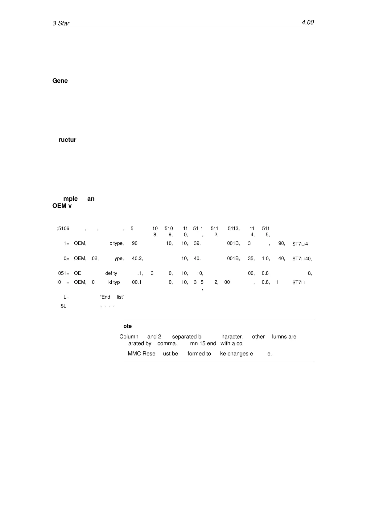
Note
Columns 1 and 2 are separated by a “=” character. All other columns are
separated by a comma. Column 15 ends with a comma.
An MMC Reset must be performed to make changes effective.
General
Structure
Example of an
OEM valve list
3 Startup
04.00

Table of Contents

Other manuals for Siemens Sinumerik 840D Series

Questions and Answers:

Question and Answer IconNeed help?

Do you have a question about the Siemens Sinumerik 840D Series and is the answer not in the manual?

Siemens Sinumerik 840D Series Specifications

General IconGeneral
AxesUp to 31 axes
Power Supply24 V DC
Control TypeCNC
InterfaceEthernet, PROFIBUS
DisplayTFT color display
PLCIntegrated PLC (programmable logic controller)
Operating Temperature0°C to 45°C
Relative HumidityUp to 95% (non-condensing)
Max. Number of ChannelsUp to 10 channels

Related product manuals