10.03
A.1 Servo solenoid valves
A-247
Siemens AG, 2003. All rights reserved
SINUMERIK 840D/SIMODRIVE 611 digital, HLA Module (FBHLA) - 10.03 Edition
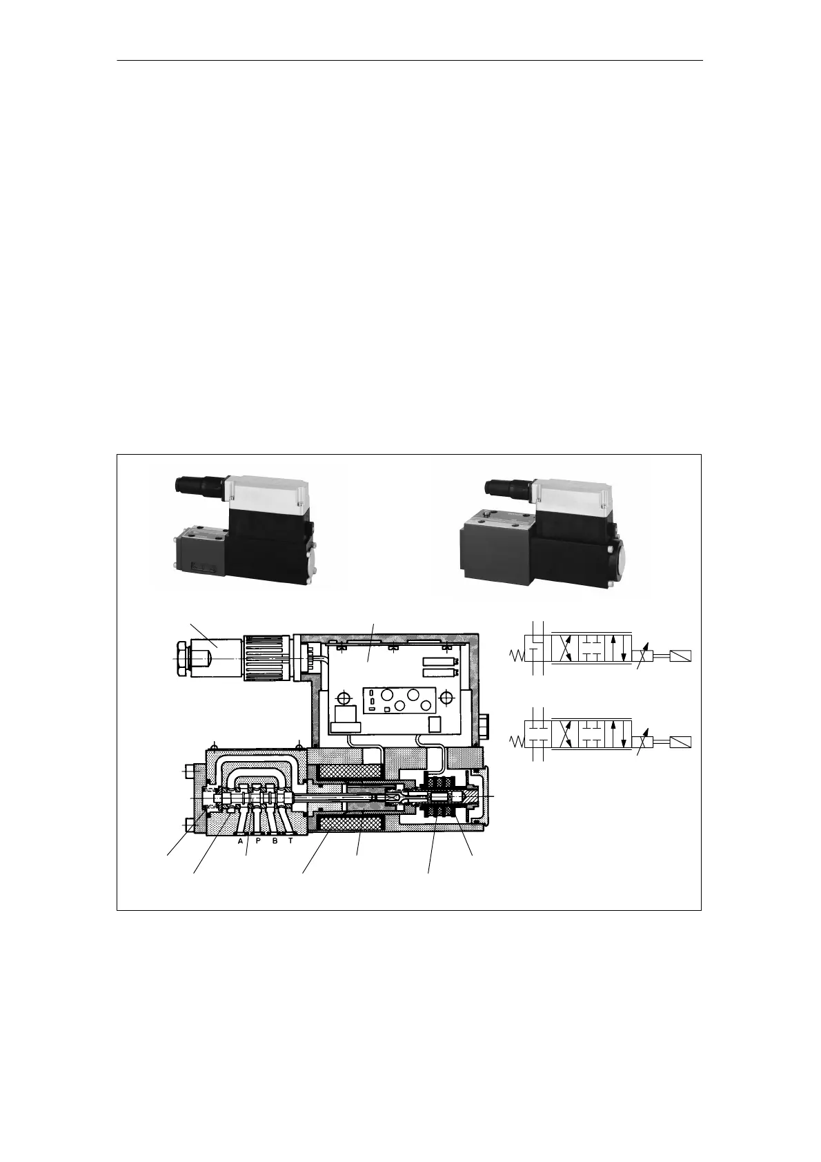
A.1.2 Directly-controlled servo solenoid valves, sizes 6 and 10
The standard series of Bosch Rexroth size 6 and 10 servo solenoid valves
shown in the following diagram are based on the same principle.
The valve spool in its steel sleeve is pushed against the reset spring directly by
the actuating solenoid. The armature axis of the solenoid is mechanically
coupled to the ferrite core of the position sensor integrated in the solenoid.
This sensor is a proximity-type, wear-resistant differential transformer ( LVDT).
The housing of the integrated valve amplifier (On Board Electronic OBE) is
bolted directly onto the solenoid/position sensor module.
Electrical power is supplied and the setpoint injected via a 7-pin connector.
If the valve is operating around the mid-position, the solenoid is energized by
about 50%. When the power supply is switched off, it assumes a 4th position,
known as the fail-safe position. On connection and disconnection of the supply,
it slides through the crossed position.
The valves are available with a variety of nominal flow rates and two different
fail-safe positions.
7-pin connector Valve amplifier
Valve spool
Steel sleeve
Actuating
solenoid coil
Reset spring
Actuating
solenoid
armature
LVDT coils
LVDT ferrite core
Size 6
Size 10
OB
PT
OB
PT
Fail-safe closed
Fail-safe open
Fig. A-13 Directly-controlled servo solenoid valves, sizes 6 and 10 (Rexroth)
Mechanical
structure

 Loading...


