10.03
3.11 Start-up functions
3-88
Siemens AG, 2003. All rights reserved
SINUMERIK 840D/SIMODRIVE 611 digital, HLA Module (FBHLA) - 10.03 Edition
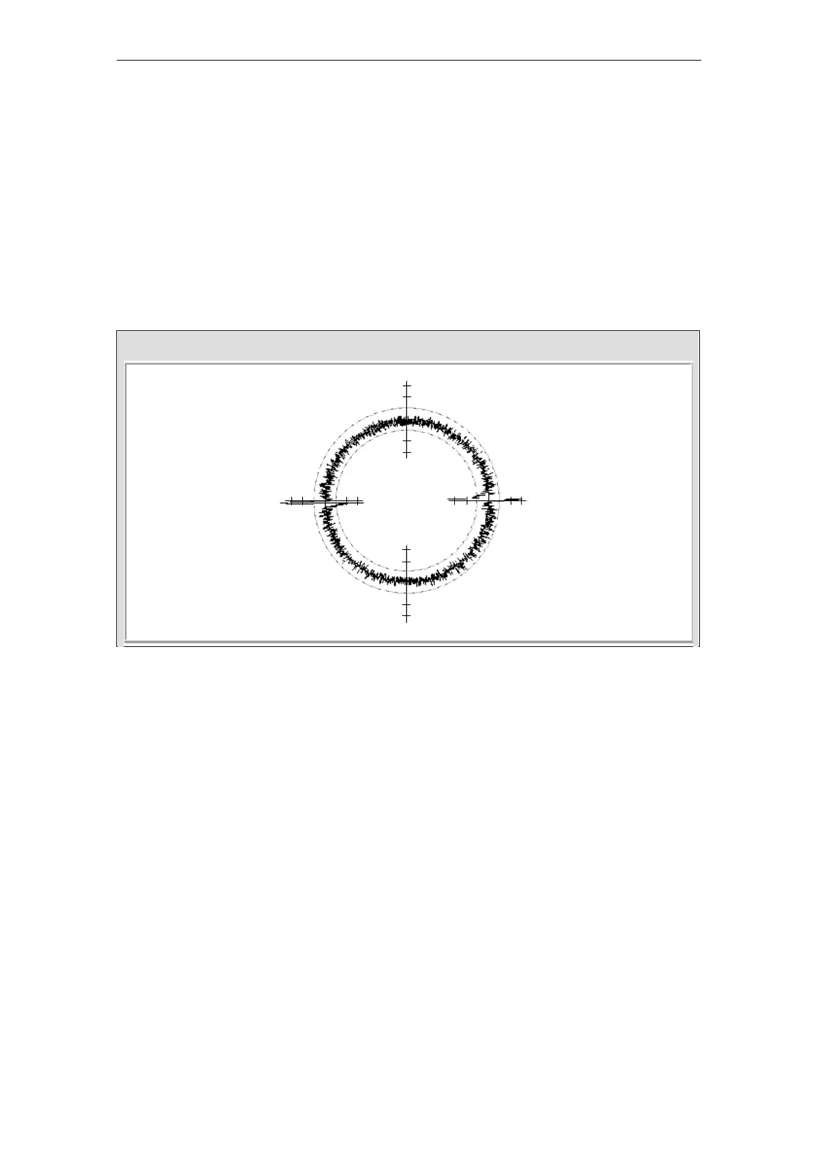
3.11.3 Circularity test
The circularity test is used among other things as a way of checking the result-
ing contour precision. It works by measuring the actual positions during a circu-
lar movement and displaying the deviations from the programmed radius as a
diagram (especially at the quadrant transitions). For detailed information, see:
References: /FB/Part 2, K3, Sect. 2.7 “Circularity test”
Example: The following example refers to a drive with an HRV.
X1 axis: Horizontal movement by electric drive
Y1 axis: Vertical movement by hydraulic drive
Scl/Div = 1.000e-03 Radius = 19.999
Tr. 1: X1 axis: Circularity test (electric axis)
Tr. 2: Y1 axis: Circularity test (hydraulic axis)
Fig. 3-41 Example of circularity test on HRV size 06, 15 l/min, knee-point 60%; V=400 mm/min (traversing velocity)
3.11.4 Servo trace
The servo trace function is used for graphic representation of signals and oper-
ating conditions.
A hydraulic-specific signal list (servo and drive signals) is available as a support
function for axes with HLA module.
The following hydraulic-specific drive signals are supported by the servo trace:
S Active power (with pressure sensing)
S Actual force (with pressure sensing)
S Actual velocity value
S Valve stroke setpoint
S Actual valve stroke
S Actual pressure cylinder A end
S Actual pressure cylinder B end
04.00
 Loading...


