10.03
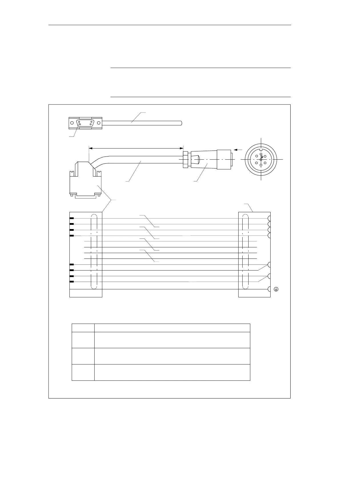
7.4 Connection diagrams for servo solenoid valves
7-232
Siemens AG, 2003. All rights reserved
SINUMERIK 840D/SIMODRIVE 611 digital, HLA Module (FBHLA) - 10.03 Edition
7.4 Connection diagrams for servo solenoid valves
Note
The following cable data for hydraulic systems is designed for directly and pilot
actuated Bosch Rexroth servo solenoid valves (see Subsection 2.3.2).
+24 V switched
UIST1N
Length according to length code
2
3
1
Sub D male connector, 15-pin, with screw lock UNC 4-40
6FC9341-1HC
bk
bn
wh-ye
rd
wh-bk
or
wh-bu
USOLL1N
P24RV1
UIST1P
M24EXT
D
O
I
F
B
C
Housing
Setpoint output +/- 10 V
+24 V switched
Setpoint output, ground
Actual value input +/-10 V
24 V external ground
Actual value input, ground
24 V external ground
HLA module
6
3
15
10
14
9
Item Meaning
7-pin socket connector
GE.570102.0144.00
Signal lead 4x(2x0.38) + 4x0.5 C
6FX2008-1BD21
1
2
3
7
4
Order No. (MLFB) of signal lead for 7-pin servo solenoid valve: 6FX2002-2BA00-1 VVV
Pin 1
Cable print (order no., length in m, manufacturer,
month/year of manufacture)
USOLL1P
P24RV1
M24EXT
wh-rd
Servo solenoid valve
Note: Max. approved system cable length 40 m
3
O
FB
CI
D
bu
vt
ye
gn
0,38
0,38
0,5
0,38
0,5
0,38
0,5
0,38
Shield
0,5
0,38
0,38
0,38
Cen.
Z 2:1
Fig. 7-11 7-pin signal lead for servo solenoid valve (X121/X122) - standard version
7 Peripherals/Accessories

 Loading...


