10.03
2.4 Connection
2-48
Siemens AG, 2003. All rights reserved
SINUMERIK 840D/SIMODRIVE 611 digital, HLA Module (FBHLA) - 10.03 Edition
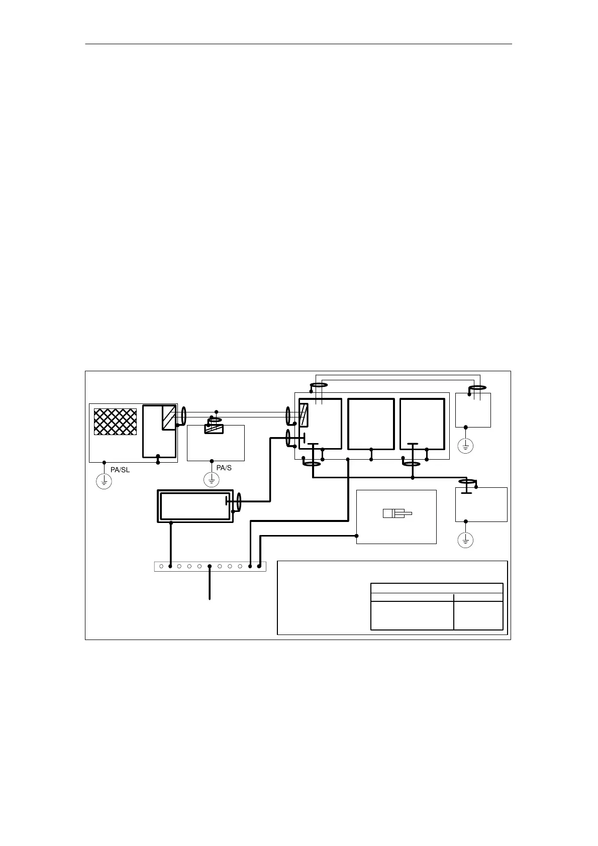
2.4.3 Grounding concept/Electromagnetic compatibility (EMC)
The 840D system with HLA module consists of a number of individual
components. The individual system components are:
S I/RF infeed/regenerative feedback module
S NCU box
S HLA module
S Machine control panel MCP
S Qwerty keyboard
S Operator panel components (various monitors with different MMC CPUs)
S Terminal block (NCU and L2 DP)
S Distributor box and handheld unit
The individual modules are attached to a metal cabinet panel by means of
screws. Make sure that near the screws a low-impedance contact of the NCU
box with the cabinet wall can be made. Insulating varnishes must be avoided
where possible.
The electronic grounding points of the modules are interconnected via the de-
vice and drive bus and at the same time conducted to the X131 terminal of the
I/RF module.
The internal electronics ground of the HLA module is directly connected to the
metal front (module) plate.
Operator panel
PA/SL
PA/SL
HLA module
Machine bed
Grounding bar
Ground terminal
PA/SL
PA
Gating
electronics
NCU
Machine
control panel
S7-300 I/Os
PA
MB
MB: Shielded signal cable with reference ground
PA: Equipotential bonding conductor
SL: Protective conductor
- Ground (frame) -
MMC
PA/SL
Terminal
block
PA/SL
Distribu-
tion box
Cross-sections (mm
2
)
10
Line supply connection S
PE minimum
S v 16
16 t S v 35
S u 35
S
16
S/2
MB
Hydraulic drive
Fig. 2-17 Grounding concept
Please note the following in relation to electromagnetic compatibility:
References: /EMC/, EMC Installation Guidelines
Standards according to Declaration of Conformity (Appendix E)
J
02.99

 Loading...


