3-49
Siemens AG, 2003. All rights reserved
SINUMERIK 840D/SIMODRIVE 611 digital, HLA Module (FBHLA) - 10.03 Edition
Installation and Start-Up
3.1 Overview of start-up process
Selection list:
valve data
Controller
data
Data entry
Calculate
controller data
Calculate drive
model data
Model
data
Selection from
a list
Cylinder data
Mechanical
data
Data input Data entry
Fig. 3-1 Overview of start-up process
Specially designed start-up menu displays are provided by the
SINUMERIK 840D control system.
Instructions for calling menu displays can be found in:
References: /IAD/, Installation and Start-Up Guide
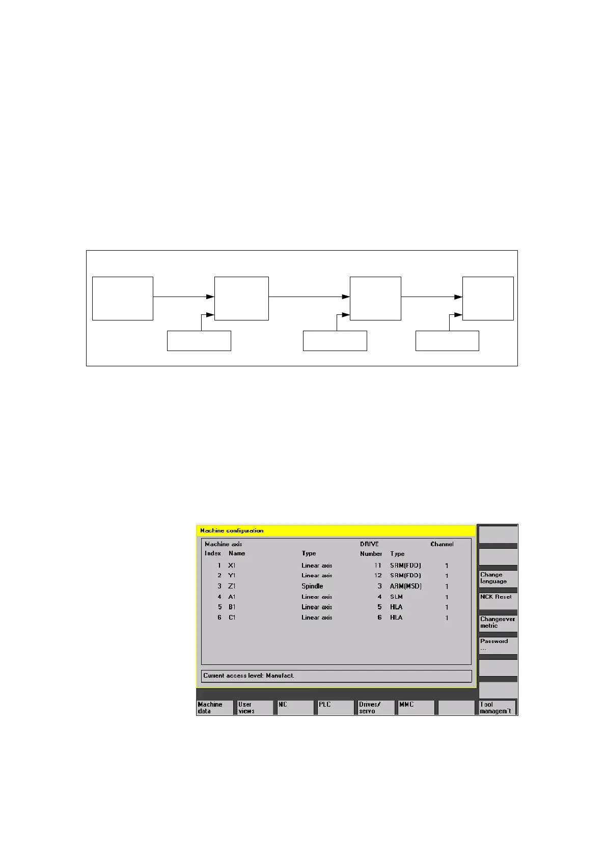
The hydraulic linear drive (HLA) is displayed as follows next to the electric
drives (SRM, ARM and SLM) in the “Machine Configuration” screen (basic
start-up display):
Fig. 3-2 Machine Configuration (basic start-up display)
Machine
Configuration
3

 Loading...


