10.03
2.1 Configuring steps
2-22
Siemens AG, 2003. All rights reserved
SINUMERIK 840D/SIMODRIVE 611 digital, HLA Module (FBHLA) - 10.03 Edition
Abbreviations,
terms and index
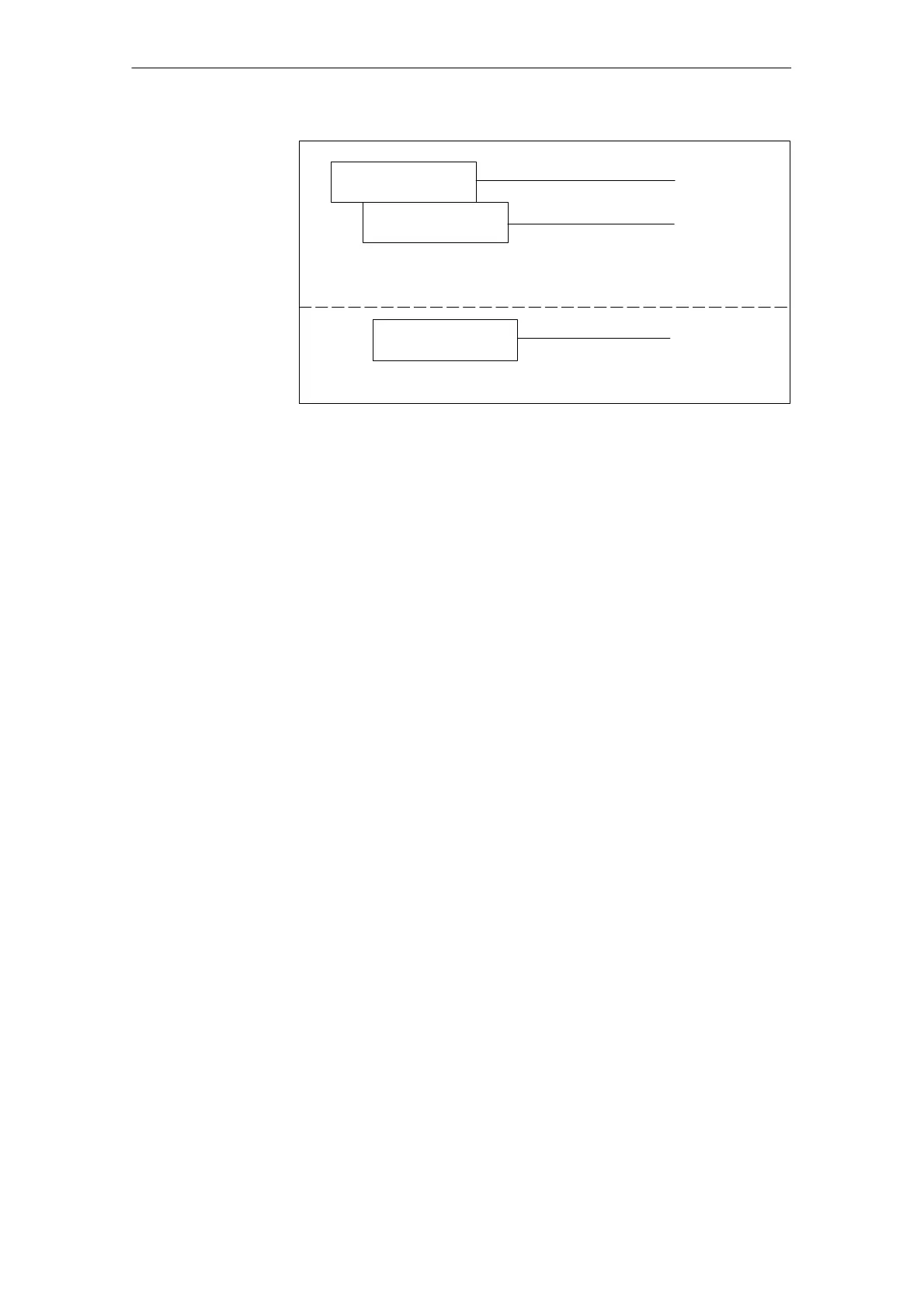
Section 2.4
Section 2.2
Appendix
Recommended circuits
EMC measures
Block diagrams/
connection diagrams
Fig. 2-2 2. configuring phase
2.1.2 Procedure for configuring hydraulic components
Hydraulically controlled drives are normally configured by the technical sales
and marketing personnel of the hydraulics supplier (e.g. Bosch
Rexroth, see Chapter 8) in close co-operation with the machine manufacturer.
This configuring phase is divided into the following steps:
S Selection of the cylinder on the basis of forces and velocities required and
the cylinder mounting conditions in the machine
(see Subsection 2.3.1).
S Selection of the servo solenoid valves on the basis of the cylinder data,
forces, velocities and dynamic requirements (see Subsection 2.3.2, 2.3.3).
S Selection of the position measuring system and optionally the pressure sen-
sors with regard to the measuring range, accuracy and linearity (see Section
7.1, 7.3).
S Dimensioning of the hydraulic power unit, taking all loads into account (see
Subsection 2.3.5).
S Calculation of the natural frequency of the drive for an initial assessment of
whether the expected control result can be achieved (see Subsection 2.3.4).
S In difficult cases, it may be worthwhile carrying out a dynamic simulation of
the drive as an aid to configuration.
The basic data required to design a system are obtained from a question-
naire.
Phase 2

 Loading...


