10.03
2.2 Integration in SINUMERIK 840D/SIMODRIVE 611 digital
2-24
Siemens AG, 2003. All rights reserved
SINUMERIK 840D/SIMODRIVE 611 digital, HLA Module (FBHLA) - 10.03 Edition
2.2 Integration in SINUMERIK 840D/SIMODRIVE 611 digital
2.2.1 System overview
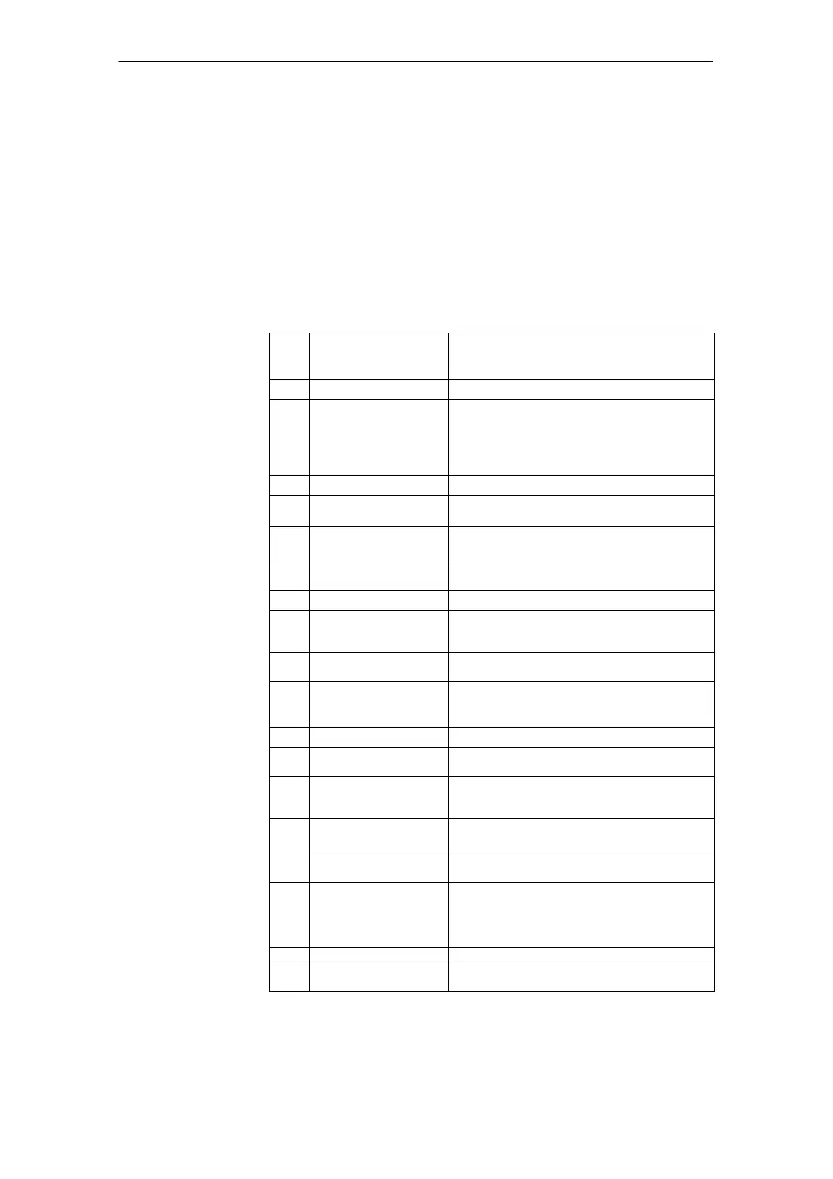
A complete SINUMERIK 840 digital control system with HLA module consists of
various individual components. These are listed below.
Table 2-1 Components of SINUMERIK 840 digital control with HLA module (number,
component, description)
No.in
Fig.
2-3
Component Description
O NCU box
S Enclosure for NC CPU
B NC CPU
S Central processing unit of 840D
S Execution of NC program,
S Contains modules with e.g. PLC, communications
functions
S NCU 573.2 includes a fan module
B1 Cable distributor
S For insertion in NCU
C
1)
Operator panel
S Display, keyboard, power supply unit and
operator controls for NC
D
1)
MMC module
S Operator panel calculator (integrated in panel),
S MMC 103 with hard disk
I Mains supply module
(MS)
References: /PJ1/ SIMODRIVE 611
F
1)
Machine control panel
S Machine operation
G1
1)
ISA adapter
S Allows AT modules to be used in conjunction with
the MMC module MMC103 (mounted in operator
panel)
G2
1)
Full CNC keyboard
S Full keyboard for connection to MMC module
G3 Memory card (PCMCIA)
S Contains the system program,
S can be slotted into the NCU 561.2, 571.2, 572.2,
573.2
G4 Diskette unit (accessory)
S Built-in unit for connection to MMC module
H1 to
H 9
Cable References: /Z/, Catalog of Accessories NC Z
H10
to
H12
Cable See Chapter 7, Peripherals/Accessories
I SIMODRIVE hydraulics
module (HLA module)
S Closed-loop control of hydraulic drive
S Actuation of servo solenoid valve
50 mm carrier module
(universal empty housing)
Holder for HLA closed-loop control plug-in module
(see Fig. 2-6)
I1 Phoenix cable connection
S Shutoff valve
S External 24 V supply
S BERO input
S “Power enable”
J SIMATIC components References: /S7H/, Manual
K Terminator Terminator for drive bus (inserted in last module in
drive grouping)
Components
02.99

 Loading...


