10.03
5.1 Interface overview
5-183
Siemens AG, 2003. All rights reserved
SINUMERIK 840D/SIMODRIVE 611 digital, HLA Module (FBHLA) - 10.03 Edition
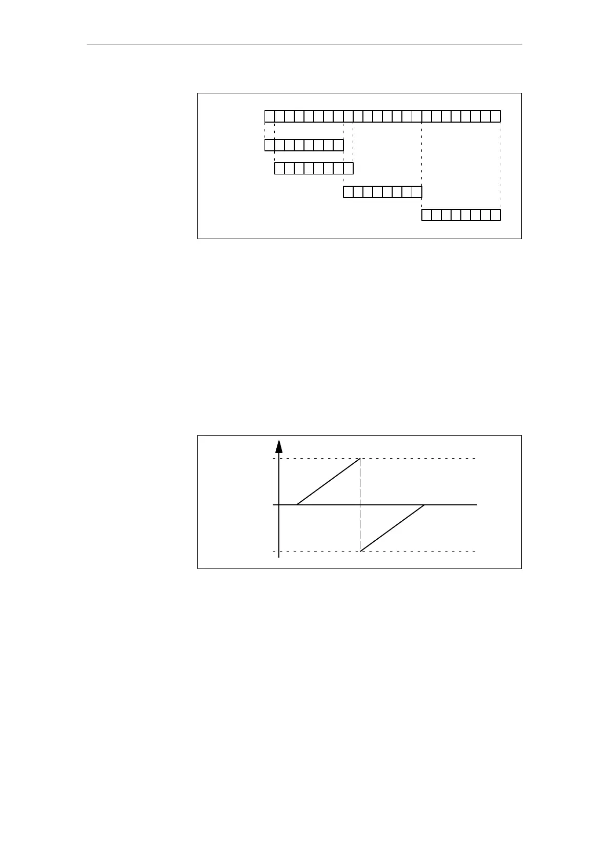
SF = Shift Factor
023Bit 781516 (LSB
DAC with SF0
DAC with SF1
DAC with SF8
DAC with SF16
LSB = Least Significant Bit
Fig. 5-3 Representation of the shift factor
The display for activating and setting the parameters of the DAC outputs is
called up from the basic machine display by pressing the Start-up /
Drive/Servo / Configur. DAC soft keys.
Use the Start soft key.to activate the configuration. Active DACs are identified
(active/inactive) on the left of the display. The output is ended with Stop (active/
inactive).
The selected signals are active after POWER ON.
The DAC operates on a voltage of between 0 V and +5 V. The 2.5 V output volt-
age corresponds to the zero point of the displayed signal. A two’s complement
is used in the digital/analog conversion, see Fig. 5-3.
2.5V
+5V
0V
7F
Hex
( 0111 1111
d
)
80
Hex
(1000 0000
d
)
FF
Hex
00
Hex
00
Hex
U
DAC
Fig. 5-4 Analog output voltage range
5.1.6 Bus interfaces
(see SIMODRIVE 611A/D)
S X141: Input
S X341: Output
A bus terminator must be plugged into the last module.
(see SIMODRIVE 611A/D)
S X151: Device bus
Activating the
analog output
Output voltage
range
Drive bus
Device bus
5 Hardware Drive Functions
04.00
 Loading...


