2-21
Siemens AG, 2003. All rights reserved
SINUMERIK 840D/SIMODRIVE 611 digital, HLA Module (FBHLA) - 10.03 Edition
Configuration
2.1 Configuring steps
2.1.1 Procedure for configuring electrical components
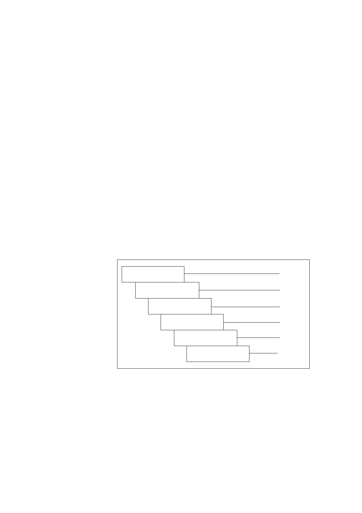
The procedure for configuring an HLA module is divided into steps in such a
way that the user is guided through the full range of relevant settings, from the
required force, to the hydraulics components, and finally the HLA and its en-
coder evaluation circuitry. This initial configuring phase may be followed by a
second in some cases, in which the corresponding circuit recommendations
and EMC measures are taken into account.
The functions of SIMODRIVE components are described with keywords in this
Planning Guide. Limit values for functions may be specified in some cases.
For further details (e.g. characteristics), please refer to the Installation and
Start-Up Guides for SIMODRIVE 611 digital and SINUMERIK 840 digital.
Further configuring instructions and detailed ordering information can be found
in Catalogs NC 60 and NC Z.
and publication from Bosch Rexroth AG
Section 2.2
Section 2.4
Selection of hydraulic
components
Dimensioning of incoming
mains supply
Dimensioning of
power modules
Chapter 4
Dimensioning of closed-
loop control components
Dimensioning of position
sensor (measuring system)
Section 7.1
Dimensioning of external
power supply
Section 2.3
and publication 6SN1197-0AA00
Section 2.2
and publication 6SN1197-0AA00
Fig. 2-1 Configuring steps in start-up sequence
Phase 1
2

 Loading...


