4-95
Siemens AG, 2003. All rights reserved
SINUMERIK 840D/SIMODRIVE 611 digital, HLA Module (FBHLA) - 10.03 Edition
Firmware Drive Functions
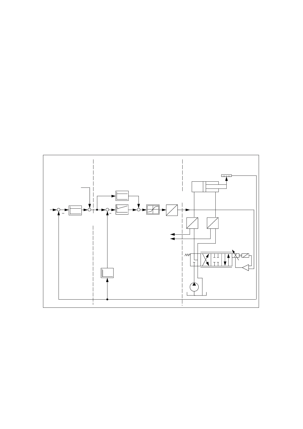
4.1 Block diagram of closed-loop control
The following diagram shows how the HLA module is embedded between the
control system and the hydraulic drive. The control functions of the module are
shown in greatly simplified form. They are shown in more detail in the diagram
on the following page.
D
O
Control Drive
OB
Velocity feedforward
control v’
forw
HLA module
Flow feedforward
control
Velocity controller
Actual
velocity v
act
Actual
position x
act
Position
setpoint x
set
Position
controller
Velocity
setpoint v
set
Characteristics
compensation
Valve setpoint
voltage U
set
Cylinder
Actual position value
Servo solenoid valve
PT
Pressure supply
Valve
amplifier
P
U
P
U
p
A
p
B
Fig. 4-1 General block diagram of NC - HLA module - drive system
The dynamic response is dependent on:
S Natural frequency of the servo solenoid valve (see Subsection 2.3.2)
S Natural frequency of the drive (see Subsection 2.3.4)
The greater the natural frequency, the better the achievable dynamic response.
For the purpose of oscillation damping, the natural frequency of the servo sole-
noid valve must be greater than that of the drive.
Integration in
overall system
Possible
dynamic response
4
 Loading...


