10.03
4.1 Block diagram of closed-loop control
4-96
Siemens AG, 2003. All rights reserved
SINUMERIK 840D/SIMODRIVE 611 digital, HLA Module (FBHLA) - 10.03 Edition
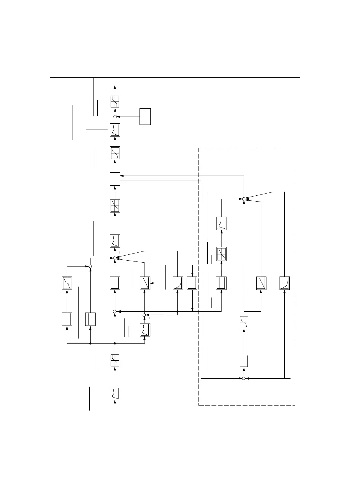
Fig.4-2 shows the functionality for velocity and closed-loop force control plus
characteristics implemented in the HLA module.
setpoint v
Velocity
Setpoint
limitation
Velocity
set
P component
MD 5409
D component
Limitation
Area adapt-
Adaptation
Adaptation
Friction injection
Flowrate feedforward control
+
Setpoint filter
Reference
MD 5460/MD 5461
MD 5435
MD 5440/
MD 5441
MD 5500-MD 5502/
MD 5506/MD 5507/
MD 5514-MD 5516/
MD 5520/MD 5004
MD 5406-MD 5408
MD 5414/
I component
MD 5430-MD 5433
Control output filter
MD 5200-MD 5205/
MD 5210-MD 5215
MD 5462
Knee-point
compensation
Manipulated voltage
limitation
to
DAC
Offset
Selection
logic
ation
MD 5463
MD 5464-MD 5468
MD 5480-MD 5488
MD 5474
Actual velocity v
Actual position x
model
MD 5415
act
act
P component
Adaptation
Adaptation
I component
Attenuation
(valve dynamic response)
F
D component
Adaptation
(see Section 4.4, Fig. 4-11)
only if pressure sensor system is connected
MD 5245/MD 5246
MD 5244
MD 5243
MD 5242
Feedforward control
MD 5247
set
F
act
Force controller
MD 5230-MD 5235
MD 5241 (configuration)
Control output filter
MD 5280/5281
MD 5284/5285
MD 5288-MD 5290
Feedforward control filter
MD 5260/5261
MD 5264/5265/MD 5268-MD 5270
control
Area adapt-
ation
Velocity controller
MD 5475
MD 5470
MD 5241
factor
Fig. 4-2 Controller and characteristic functions of the HLA module
Block diagram of
control functions
4 Firmware Drive Functions
 Loading...


