10.03
7.4 Connection diagrams for servo solenoid valves
7-233
Siemens AG, 2003. All rights reserved
SINUMERIK 840D/SIMODRIVE 611 digital, HLA Module (FBHLA) - 10.03 Edition
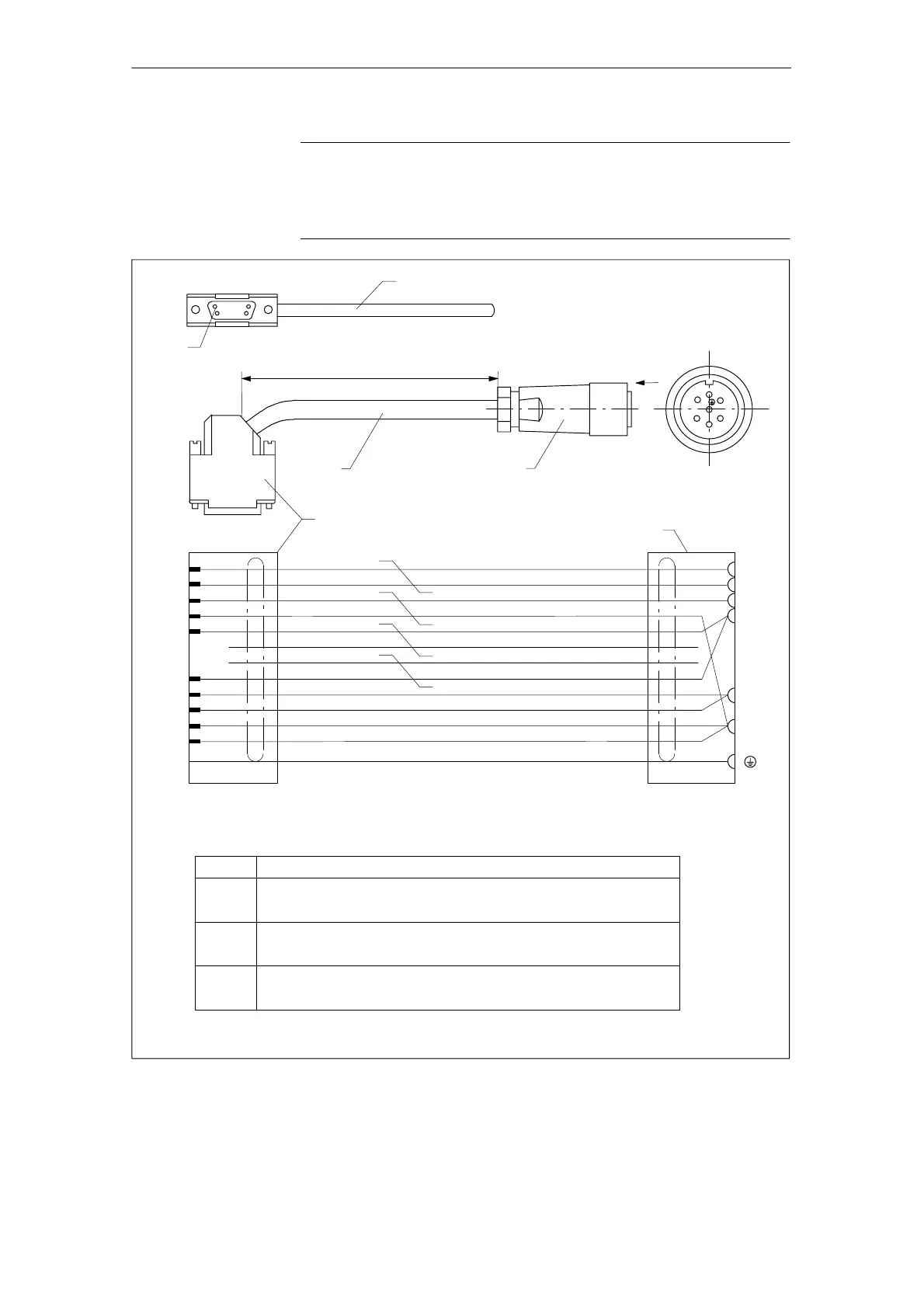
Note
The pin assignments on valves supplied by other manufacturers may deviate
from the assignments shown in Fig. 7-11. Cables must be assembled by the
customer!
+24 V switched
UIST1N
Length according to length code
2
3
1
Sub D male connector, 15-pin, with screw lock UNC 4-40
6FC9341-1HC
bk
bn
wh-ye
rd
wh-bk
or
wh-bu
USOLL1N
P24RV1
UIST1P
M24EXT
D
O
I
F
B
C
Housing
Setpoint output +/- 10 V
+24 V switched
Setpoint output, ground
Actual value input +/-10 V
24 V external ground
Actual value input, ground
24 V external ground
HLA module
6
3
15
10
14
9
Item Meaning
7-pin socket connector
Valve-specific
Signal lead 4x(2x0.38) + 4x0.5 C
6FX2008-1BD21
1
2
3
7
4
Pin 1
Cable print (order no., length in m, manufacturer,
month/year of manufacture)
USOLL1P
P24RV1
M24EXT
wh-rd
Servo solenoid valve
Note: Max. approved system cable length 40 m
3
O
FB
CI
D
bu
vt
ye
gn
0,38
0,38
0,5
0,38
0,5
0,38
0,5
0,38
Shield
0,5
0,38
0,38
0,38
Cen.
Z 2:1
1
2
Fig. 7-12 Interconnection diagram for 7-pin servo solenoid valve (X121/X122) - connection option 2 (customized)
7 Peripherals/Accessories
 Loading...


