10.03
A.1 Servo solenoid valves
A-248
Siemens AG, 2003. All rights reserved
SINUMERIK 840D/SIMODRIVE 611 digital, HLA Module (FBHLA) - 10.03 Edition
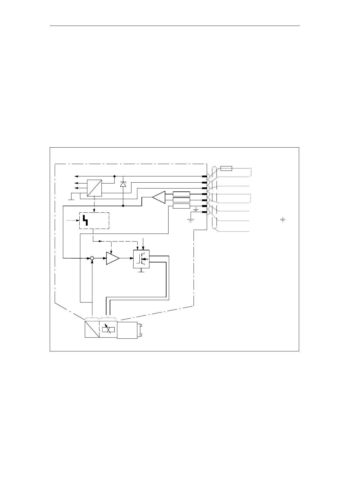
The functions of the integral valve amplifier are implemented with analog cir-
cuits, and are illustrated in the block diagram (see Fig. A-14).
The main amplifier functions are:
S Supply and evaluation of the position sensor (AC/DC converter)
S Comparison of setpoint input signal with spool actual value
S Formation of manipulated variable via a PID controller for the output stage
S Timing output stage with pulse length modulation
The amplifier is calibrated to match the valve at the factory. The zero-point is
adjusted via the NC during start-up.
+24 V=
Reference point
Setpoint 0...
Actual valve spool
Supply
Protective
Shield
2.5 AF
+
-
10 V
0 V
Actual valve spool
0 V
Sign.
+15 V
-15 V
100k
100k
10k
+U
B
DC
DC
S
U
PID
Logic
+
-
O
B
C
D
I
F
+U
B
conductor
value
value
Fig. A-14 Valve amplifier block diagram for directly-controlled servo solenoid valves, sizes 6 and 10 (Rexroth)
Valve amplifier
 Loading...


