10.03
3.14Configuring an OEM valve list
3-93
Siemens AG, 2003. All rights reserved
SINUMERIK 840D/SIMODRIVE 611 digital, HLA Module (FBHLA) - 10.03 Edition
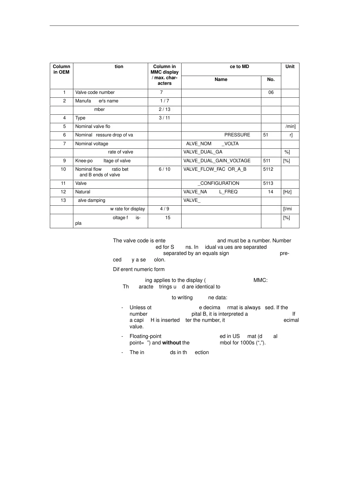
Table 3-15 Meaning of individual columns
ÁÁ
Column
in OEM
ÁÁÁÁÁÁÁ
Description
ÁÁÁ
Column in
MMC display
ÁÁÁÁÁÁÁÁÁÁ
Reference to MD
Á
Unit
valve
list
/ max. char-
acters
Name No.
1
Valve code number
7 / 5
VALVE_CODE
5106
2 Manufacturer’s name 1 / 7
3
Order Number
2 / 13
4
Type
3 / 11
5
Nominal valve flow
VALVE_NOMINAL_FLOW
5107
[l/min]
6
Nominal pressure drop of valve
VALVE_NOMINAL_PRESSURE
5108
[bar]
7
Nominal voltage of valve
VALVE_NOMINAL_VOLTAGE
5109
[V]
8
Knee-point flow rate of valve
VALVE_DUAL_GAIN_FLOW
5110
[%]
9
Knee-point voltage of valve
VALVE_DUAL_GAIN_VOLTAGE
5111
[%]
10
Nominal flow rate ratio between
A and B ends of valve
6 / 10
VALVE_FLOW_FACTOR_A_B
5112
11
Valve configuration
VALVE_CONFIGURATION
5113
12
Natural frequency of valve
VALVE_NATURAL_FREQUENCY
5114
[Hz]
13
Valve damping
VALVE_DAMPING
5115
14 Nominal valve flow rate for display 4 / 9 [l/min]
15 Valve knee-point voltage for dis-
play
5 / 15 [%]
The valve code is entered in the first column and must be a number. Numbers 1
to 1000 are reserved for Siemens. Individual values are separated by commas.
Columns 1 and 2 are separated by an equals signal (=). Comments are pre-
ceded by a semicolon.
Different numeric formats may be used.
S The following applies to the display (selection list) on the MMC:
The character strings used are identical to those stored in the INI file.
S The following applies to writing machine data:
- Unless otherwise specified, the decimal format is always used. If the
number is followed by a capital B, it is interpreted as a binary number. If
a capital H is inserted after the number, it is interpreted as a hexadecimal
value.
- Floating-point numbers must be specified in US format (decimal
point=“.”) and without the separator symbol for 1000s (“,”).
- The individual fields in this section can be left empty, i.e. they contain 2
commas one after the other or two blanks between the 2 commas.
Empty fields are not written to the drive, i.e. the default setting of the ma-
chine data is transferred unchanged. The number of blanks is optional.
The maximum permitted number of characters is shown in Table 3-15.
 Loading...


