10.03
4.12 Terminals
4-148
Siemens AG, 2003. All rights reserved
SINUMERIK 840D/SIMODRIVE 611 digital, HLA Module (FBHLA) - 10.03 Edition
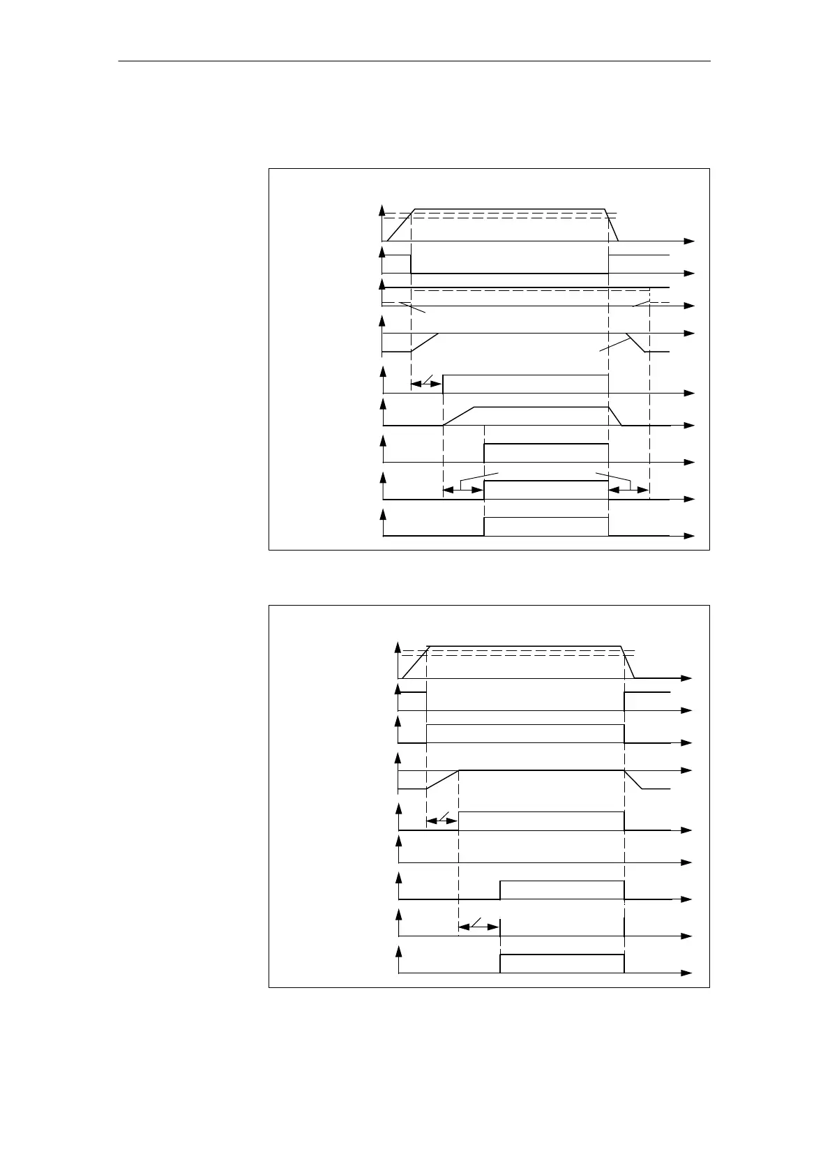
Figs. 4-19 and 4-20 show the system response to 24 V ON and OFF for a con-
figuration with and without shut-off valve.
Chronological sequence after connection of 24 V with shutoff valve
Power enable and velocity controller commands issued, setpoint > 0
24 V missing
message
Status bit
power enable
Switches
Shutoff valve
Power enable delay
Output value enable
delay
Status bit
Velocity
controller enable
closed
open
Effective
velocity
setpoint
24 V supply
Shutoff valve
open
closed
Valve spool
position
zero
Fail-safe
Backup capacitor maintains
24 V for valve electronics
Switch for servo
solenoid valve
closed
open
The valve supply is disconnected
only if bit 4 in MD 5530 is set to
supply
Fig. 4-19 Chronological sequence after connection of 24 V supply, with shut-off valve
Chronological sequence after connection of 24 V supply without shutoff valve
Power enable and velocity controller enable commands issued, setpoint > 0
24 V missing
message
Status bit
power enable
Switches
Shutoff valve
Power enable delay MD 5532
Output value delay MD 5531
closed
open
Effective
velocity
setpoint
24 V supply
Shutoff valve
open
closed
Valve spool
position
zero
Fail-safe
Switch for servo
solenoid valve
closed
open
No shutoff valve connected
Status bit
Velocity
controller enable
supply
Fig. 4-20 Chronological sequence after connection of 24 V supply, without shut-off valve
4 Firmware Drive Functions
02.99

 Loading...


