10.03
7.1 Measuring systems
7-220
Siemens AG, 2003. All rights reserved
SINUMERIK 840D/SIMODRIVE 611 digital, HLA Module (FBHLA) - 10.03 Edition
0
Direct component U
G(A)
Mech. angle ϕ
0
Mech. angle ϕ
0
Mech. angle ϕ
Differential signal (A - *A)
Direct component U
G(B)
Direct component
U
G(R)
Useful signal
Differential signal (B - *B)Differential signal (R - *R)
β
45 degrees
Uniqueness range
α1 α2
360 degrees
Electrical
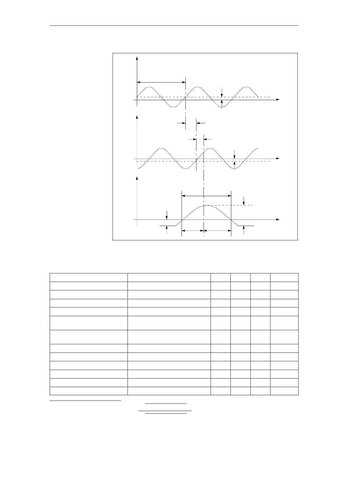
Fig. 7-2 Required signal chart of measuring system signals (incremental and
reference) after differential amplification for data function
Table 7-1 Limit data for measuring system signals
Parameters Description min. typ. max. Unit
Mean voltage U
M(A)
; U
M(B)
; U
M(R)
1.75 3.25 V
Amplitude A - *A; B - *B 350 500 600 mv
Ratio (A - *A)/(B - *B) 0.9 1.0 1.1 -
Dynamic change in amplitude ∆(A - *A)/360° el.; ∆(B - *B)/360° el. - - 0.3 mV/360° el.
Direct component U
G(A)
/amplitude (A - *A);
U
G(B)
/amplitude (B - *B);
-0.2 0 +0.2
Dynamic change in
direct component
∆U
G(A)
/360° el.;
∆U
G(B)
/360° el.
- - 1 mV/360° el.
Signal frequency fs - - 200 kHz
Phase shift β 85 90 95 Degrees
Harmonic distortion
1)
k - - 1 %
Useful signal R - *R 300 - 1500 mV
DC voltage U
direct(R)
-150 - -500 mV
Uniqueness range α1; α2 50 - 270 Degrees
1) Definition for harmonic distortion: k =
Ǹ
U1
2
+U2
2
+...Un
2
Ǹ
U0
2
+U1
2
+...Un
2
U0: Fundamental component
U1...Un: Harmonic components
7 Peripherals/Accessories
02.99

 Loading...


