10.03
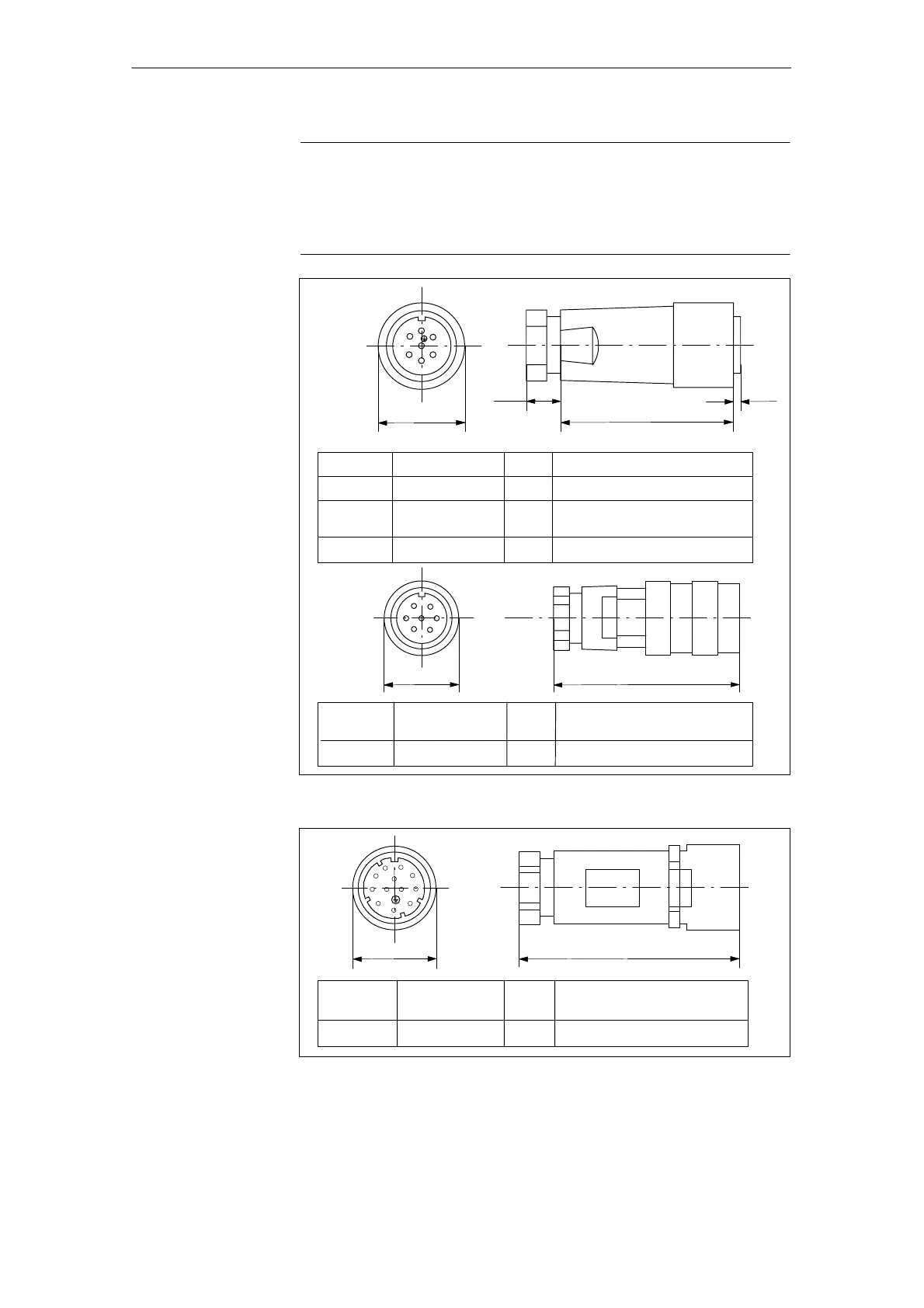
7.4 Connection diagrams for servo solenoid valves
7-235
Siemens AG, 2003. All rights reserved
SINUMERIK 840D/SIMODRIVE 611 digital, HLA Module (FBHLA) - 10.03 Edition
Note
The following data for the connectors on the servo solenoid or HR servo
solenoid valve signal leads only applies to spare parts orders or where the
cables are to be made up by the customer. The cables are normally supplied
fully pre-assembled by Siemens.
O
FB
CI
D
28.6
X10 2.6
Metal Crimp connection
0.08 Rexroth 1 834 482 023
Plastic Crimp connection 0.05 Rexroth 1 834 482 026
Plastic Soldered
connection
0.05 Rexroth 1 834 482 022
Hirschmann CM 06 EA 14S-61S
Design Contacts kg Order No.
66
7
43
2
6
1
21.5 Approx. 66
Plastic Soldered
connection
0.05 Rexroth 1 834 484 140
Binder 723-2-09-0126-25-07
Design Contacts kg Order No.
Fig. 7-14 Dimension diagram of circular, 7-pin connector
29
79
Plastic Crimp
connection
0.05 Rexroth 1 834 484 142
Hirschmann NIIR EF K B0
Design Contacts kg Order No.
8
11
7
6
5
4
1
3
2
9
10
Fig. 7-15 Dimension diagram of circular, 12-pin connector
J
7 Peripherals/Accessories
 Loading...


