10.03
A.1 Servo solenoid valves
A-240
Siemens AG, 2003. All rights reserved
SINUMERIK 840D/SIMODRIVE 611 digital, HLA Module (FBHLA) - 10.03 Edition
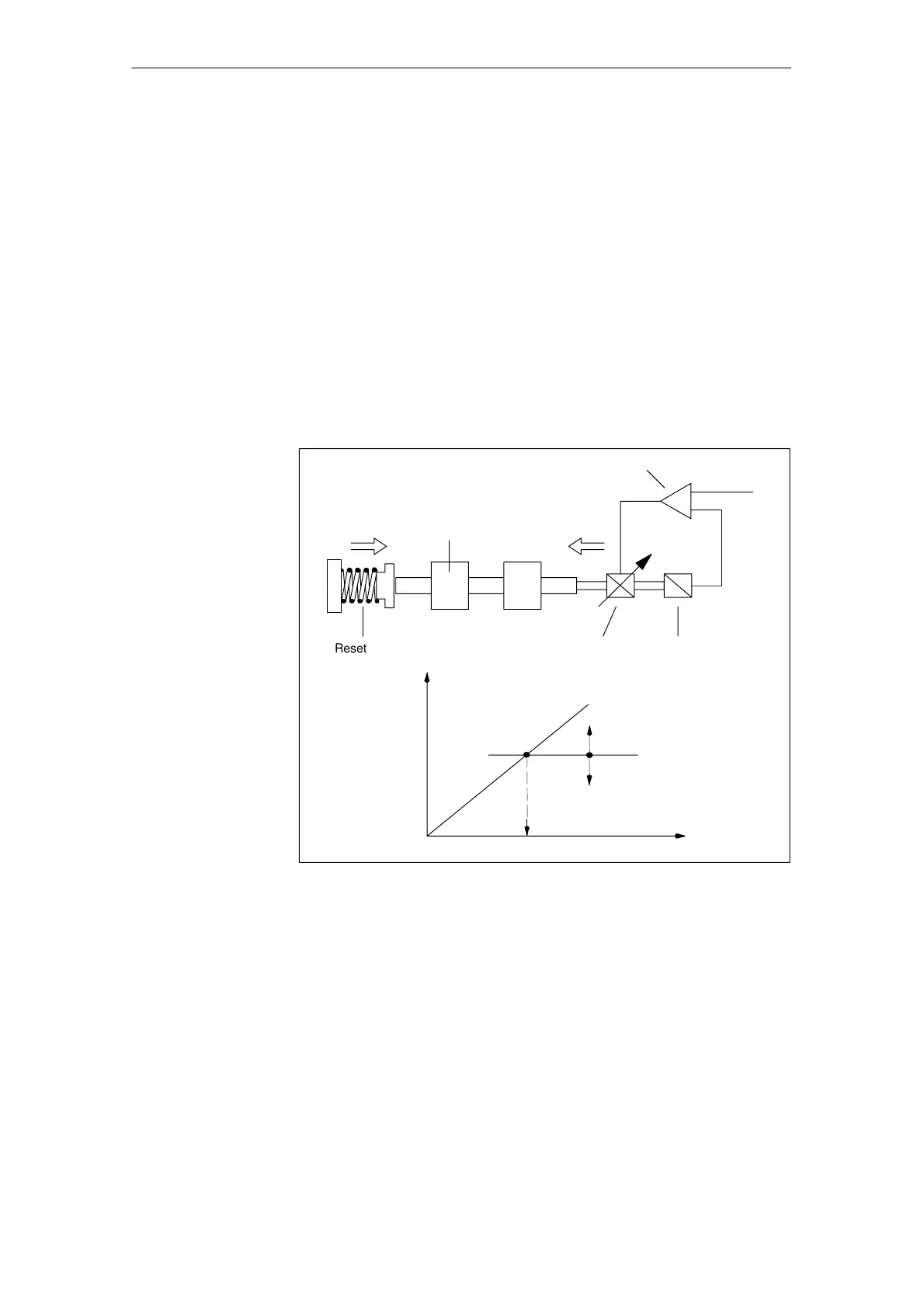
On size 6 and 10 standard servo solenoid valves, the valve spool is actuated
directly by a stepless actuating solenoid. This converts a current I into a force F,
which is compared to the force of the reset spring. This comparison of forces
finally produces a travel s, and thus an opening cross-section at the control
edges of the valve spool.
To compensate for disturbance forces acting on the valve spool (flow forces)
and to reduce the hysteresis and response sensitivity or range of inversion, the
position of the armature, and therefore the spool travel, is scanned and applied
to a position control loop as an actual value. Any deviations from the spool posi-
tion setpoint are thus continuously corrected. This method is particularly suc-
cessful in reducing the valves’ sensitivity to dirt.
Very small control deviations, such as those caused when the valve spool
sticks, can be corrected by mobilizing the entire available magnetic force.
A wear-resistant, proximity-type differential transformer (LVDT) is used as the
spool travel sensor.
Valve amplifier
Valve spoolF
F
F
M
U
E
Reset spring
Actuating
solenoid
Position
sensor
S
U
F
F
F
F
M
S
Fig. A-2 Solenoid actuation with valve spool position control
The operating principle of the servo solenoid valve is represented by a symbol
in the hydraulic circuit diagram. The symbol comprises a series of different
boxes denoting the valve positions.
The three stepless-transition valve positions are represented by additional lines.
The symbol also indicates how the valve is actuated. In this case, by direct sole-
noid actuation with spring return at one end.
If the valve has a fail-safe position, then the valve spool moves into a fourth
(safety) position when the valve is not powered. There are two alternative posi-
tions.
Solenoid actuation
with valve spool
position control
Graphical symbol

 Loading...


