EasyManuals Logo

Siemens Sinumerik 840D Series Function Manual

Siemens Sinumerik 840D Series
288 pages
To Next Page IconTo Next Page
To Previous Page IconTo Previous Page
Page #243 background imageLoading...
Page #243 background image
10.03
A.1 Servo solenoid valves
A-243
Siemens AG, 2003. All rights reserved
SINUMERIK 840D/SIMODRIVE 611 digital, HLA Module (FBHLA) - 10.03 Edition
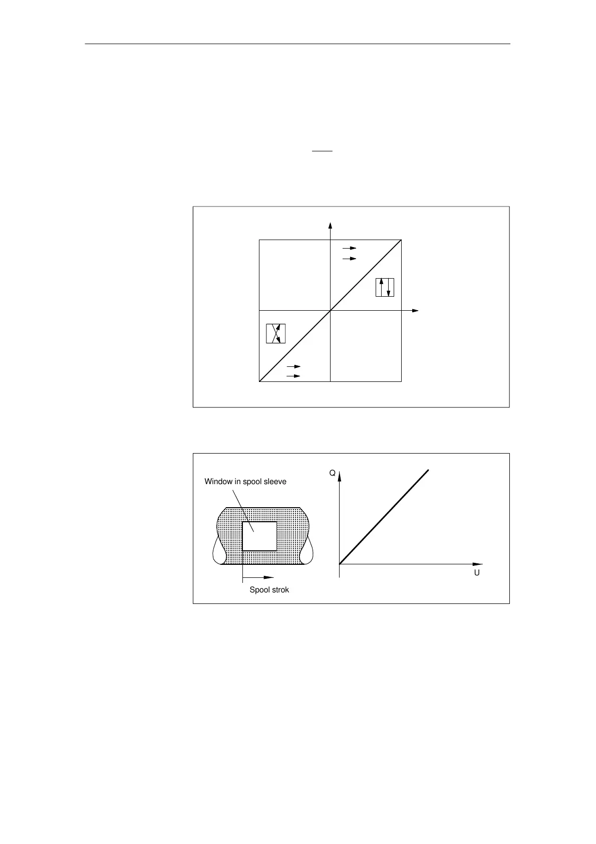
The stepless spool movement, and thus the change in throttle cross-section at
the control edges, results in a corresponding flowrate, which is represented as a
function of the spool travel s or of the electrical input signal U (manipulated vari-
able). The flow is dependent on the on the pressure drop, in addition to the
opening cross-section,
Q X
Ǹ
D
p
as defined by the law of flow.
OB
PT
P B After
O T
P O
B T
Flow rate Q
Spool travel s
Input signal U
OB
PT
Fig. A-6 Linear flow rate characteristic
ÎÎÎÎÎÎÎ
ÎÎÎÎÎÎÎ
ÎÎÎÎÎÎÎ
ÎÎÎÎÎÎÎ
ÎÎÎÎÎÎÎ
Q
U
Window in spool sleeve
Spool stroke
Fig. A-7 Control window in spool sleeve
Flow
characteristic,
linear
A Hydraulics
10.03

Table of Contents

Other manuals for Siemens Sinumerik 840D Series

Questions and Answers:

Question and Answer IconNeed help?

Do you have a question about the Siemens Sinumerik 840D Series and is the answer not in the manual?

Siemens Sinumerik 840D Series Specifications

General IconGeneral
AxesUp to 31 axes
Power Supply24 V DC
Control TypeCNC
InterfaceEthernet, PROFIBUS
DisplayTFT color display
PLCIntegrated PLC (programmable logic controller)
Operating Temperature0°C to 45°C
Relative HumidityUp to 95% (non-condensing)
Max. Number of ChannelsUp to 10 channels

Related product manuals