EasyManuals Logo

Siemens Sinumerik 840D Series Function Manual

Siemens Sinumerik 840D Series
288 pages
To Next Page IconTo Next Page
To Previous Page IconTo Previous Page
Page #251 background imageLoading...
Page #251 background image
10.03
A.1 Servo solenoid valves
A-251
Siemens AG, 2003. All rights reserved
SINUMERIK 840D/SIMODRIVE 611 digital, HLA Module (FBHLA) - 10.03 Edition
+15 V
-15 V
Reference point
Setpoint 0...
Actual valve spool
Supply
Protective
Shield
2.5 AF
100k
100k
10k
+U
B
DC
DC
S
U
PID
Logic
+
-
PD
+
-
0...
1
2
3
4
+
-
10 V
+
-
10 V
+24 V=O
B
C
D
I
F
0 V
1)
Actual valve spool
0 V
Sign.
1) Do not connect to 0 V supply
connect
+U
B
-15 V=
ref. 0
+15 V=
Signal
Main
stage
Pilot
stage
Diff.
amp.
S
U
conductor
value
value
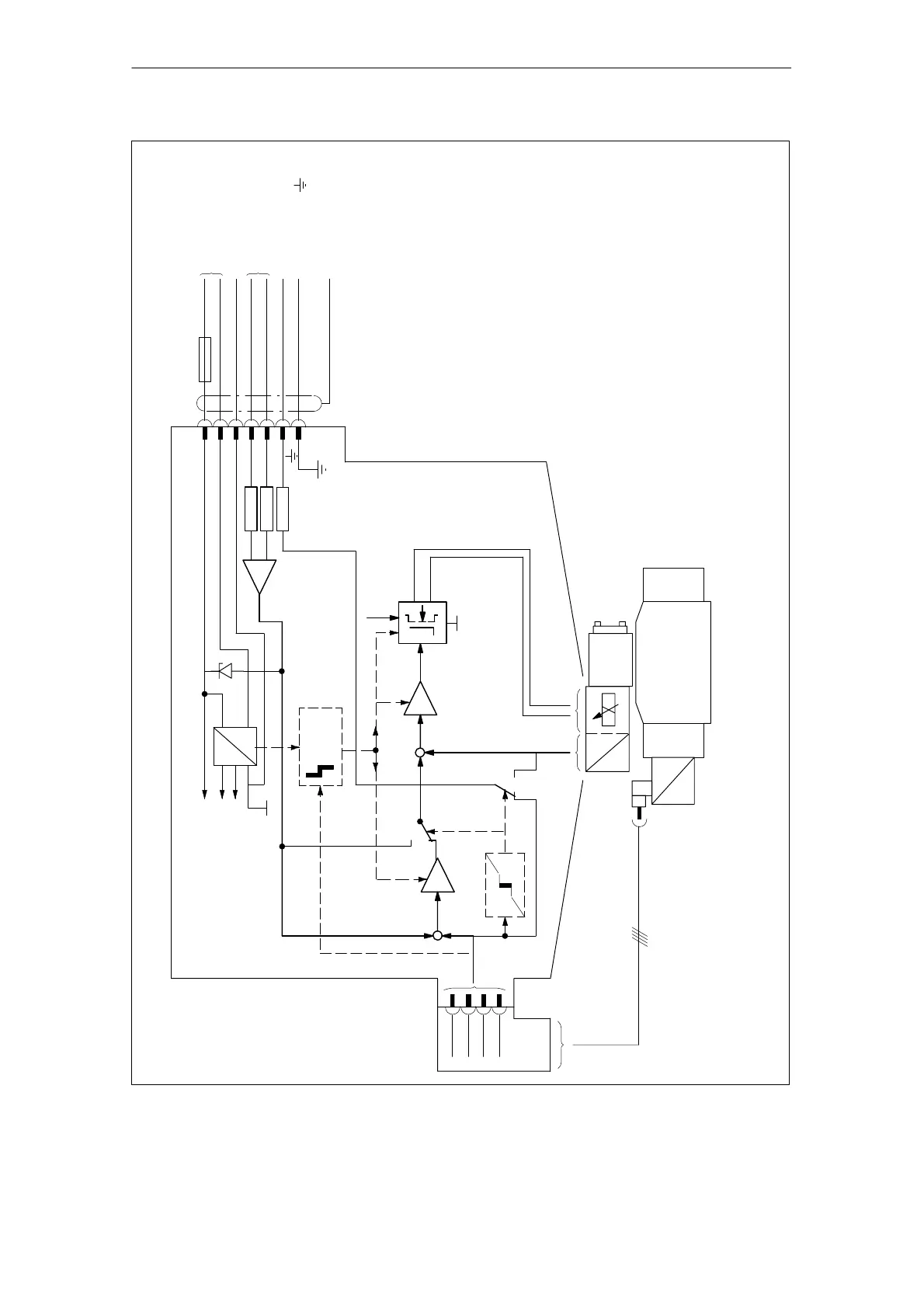
Fig. A-16 Valve amplifier block diagram for pilot-controlled servo solenoid valves, sizes 10 and 16 (Rexroth)
A Hydraulics

Table of Contents

Other manuals for Siemens Sinumerik 840D Series

Questions and Answers:

Question and Answer IconNeed help?

Do you have a question about the Siemens Sinumerik 840D Series and is the answer not in the manual?

Siemens Sinumerik 840D Series Specifications

General IconGeneral
AxesUp to 31 axes
Power Supply24 V DC
Control TypeCNC
InterfaceEthernet, PROFIBUS
DisplayTFT color display
PLCIntegrated PLC (programmable logic controller)
Operating Temperature0°C to 45°C
Relative HumidityUp to 95% (non-condensing)
Max. Number of ChannelsUp to 10 channels

Related product manuals