10.03
2.3 Configuring the hydraulic drive
2-40
Siemens AG, 2003. All rights reserved
SINUMERIK 840D/SIMODRIVE 611 digital, HLA Module (FBHLA) - 10.03 Edition
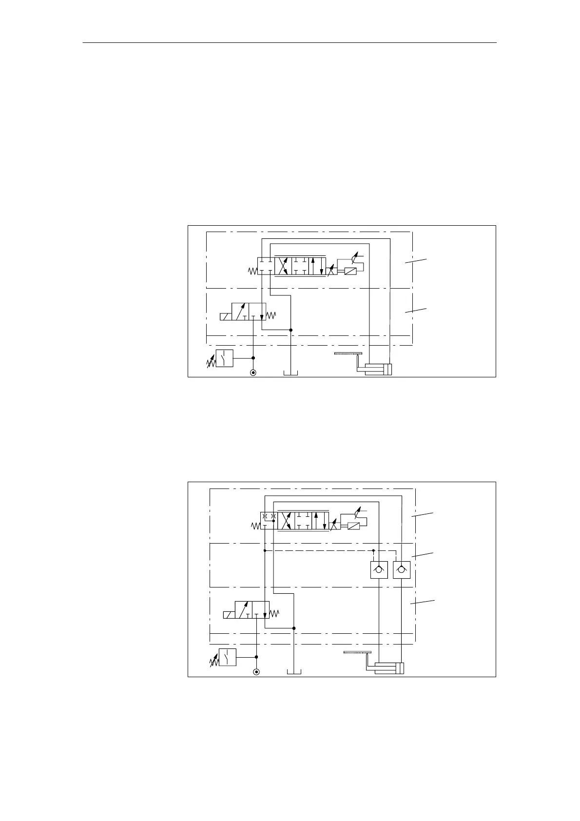
Figure 2-13 shows an electrically-switched sandwich-type shut-off valve used to
shut off the system pressure at the servo solenoid valve.
Interruption of the hydraulic power circuit upstream of the servo solenoid valve
is sufficient to meet simple safety requirements. When a servo solenoid valve in
the closed fail-safe position is switched off, then approximate shut-off of the con-
sumer connections with respect to the cylinder is guaranteed.
There are some safety limitations, however, since the servo solenoid valve’s
fail-safe position is not totally free of leakage oil, and thus does not work without
some cylinder drift. In addition, when the servo solenoid valve is switched on
and off, the “crossed” position is necessarily passed, which can result in cylin-
der movement.
OB
PT
S
U
b
T BOP
a
Servo
solenoid
valve
Shut-off valve
(electrically
switched)
Fig. 2-13 A typical example for an electrically-controlled shut-off valve
The circuit in Figure 2-14 achieves a high level of safety. In this case, an addi-
tional barrier block closes the consumer connections to the cylinder safely and
with no leakage of oil. This means that even heavy loads on non-horizontal axis
can be quickly stopped and held safely, regardless of the state of the servo so-
lenoid valve. Totally safe scenarios for switching the drive on and off can thus
be implemented.
OB
PT
S
U
b
T BOP
a
Servo
solenoid
valve
Shutoff valve
(barrier block)
Shutoff valve
(electrically
switched)
Fig. 2-14 Typical example for the combination of an electrically-switched shut-off valve
with an additional barrier block
Examples
 Loading...


