EasyManuals Logo

Siemens Sinumerik 840D Series Function Manual

Siemens Sinumerik 840D Series
288 pages
To Next Page IconTo Next Page
To Previous Page IconTo Previous Page
Page #44 background imageLoading...
Page #44 background image
10.03
2.3 Configuring the hydraulic drive
2-44
Siemens AG, 2003. All rights reserved
SINUMERIK 840D/SIMODRIVE 611 digital, HLA Module (FBHLA) - 10.03 Edition
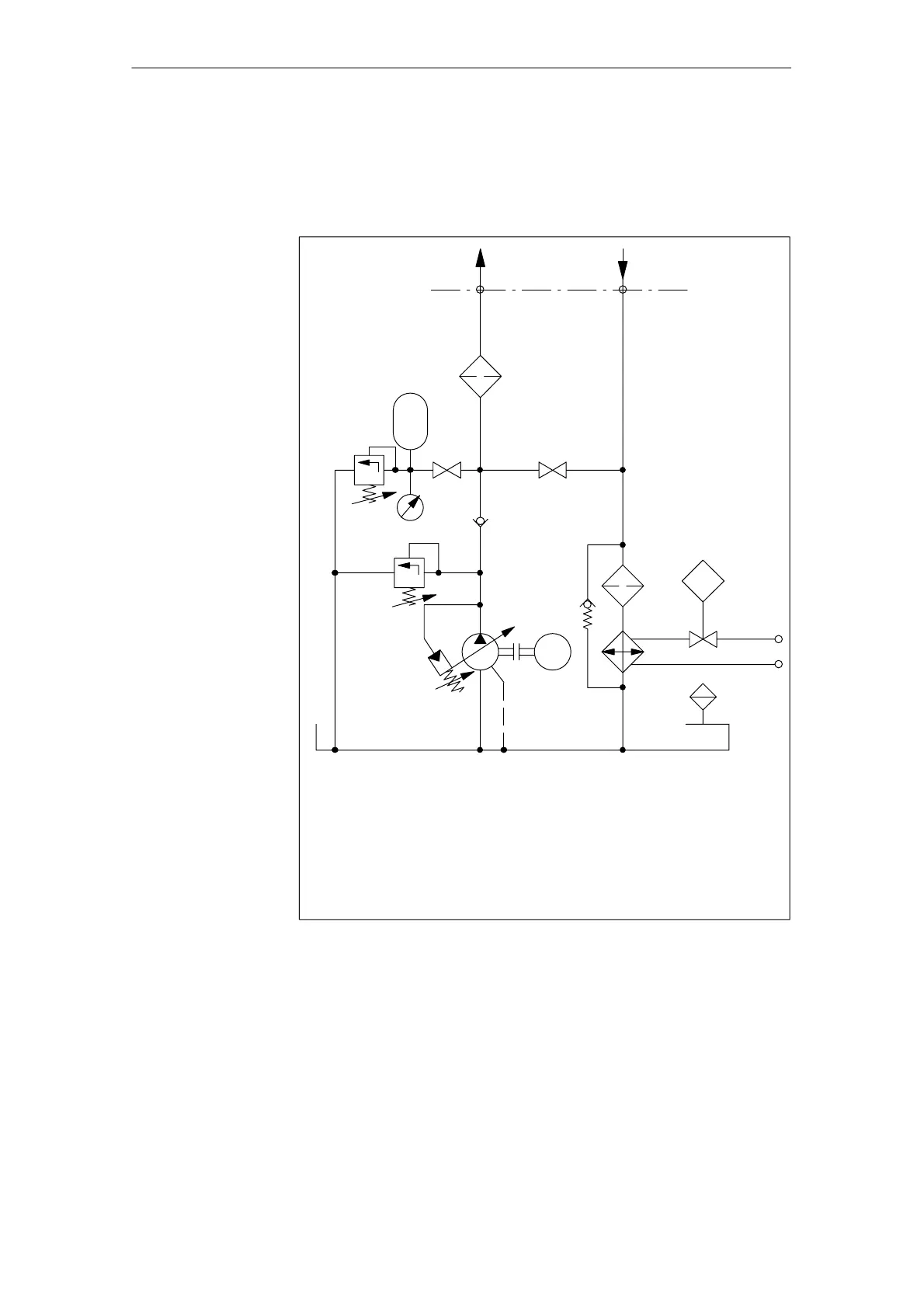
Since considerable power losses that cannot be compensated for solely
through oil reservoir dissipation occur when the flow is throttled via the control
edges on the valve, additional oil/air or oil/water heat exchangers must be pro-
vided in most cases.
°C
P
Q
M
Variable displacement pump with pressure regulator
Pressure-relief valve (protection)
Accumulator with fail-safe circuit
Filters in pressure line
Filters in return line
Oil/water heat exchanger
Oil reservoir
(GND)
Fig. 2-15 Overview of typical hydraulic power unit
Cooling
2 Configuration

Table of Contents

Other manuals for Siemens Sinumerik 840D Series

Questions and Answers:

Question and Answer IconNeed help?

Do you have a question about the Siemens Sinumerik 840D Series and is the answer not in the manual?

Siemens Sinumerik 840D Series Specifications

General IconGeneral
AxesUp to 31 axes
Power Supply24 V DC
Control TypeCNC
InterfaceEthernet, PROFIBUS
DisplayTFT color display
PLCIntegrated PLC (programmable logic controller)
Operating Temperature0°C to 45°C
Relative HumidityUp to 95% (non-condensing)
Max. Number of ChannelsUp to 10 channels

Related product manuals