10.03
3.9 Fine adjustment and optimization
3-66
Siemens AG, 2003. All rights reserved
SINUMERIK 840D/SIMODRIVE 611 digital, HLA Module (FBHLA) - 10.03 Edition
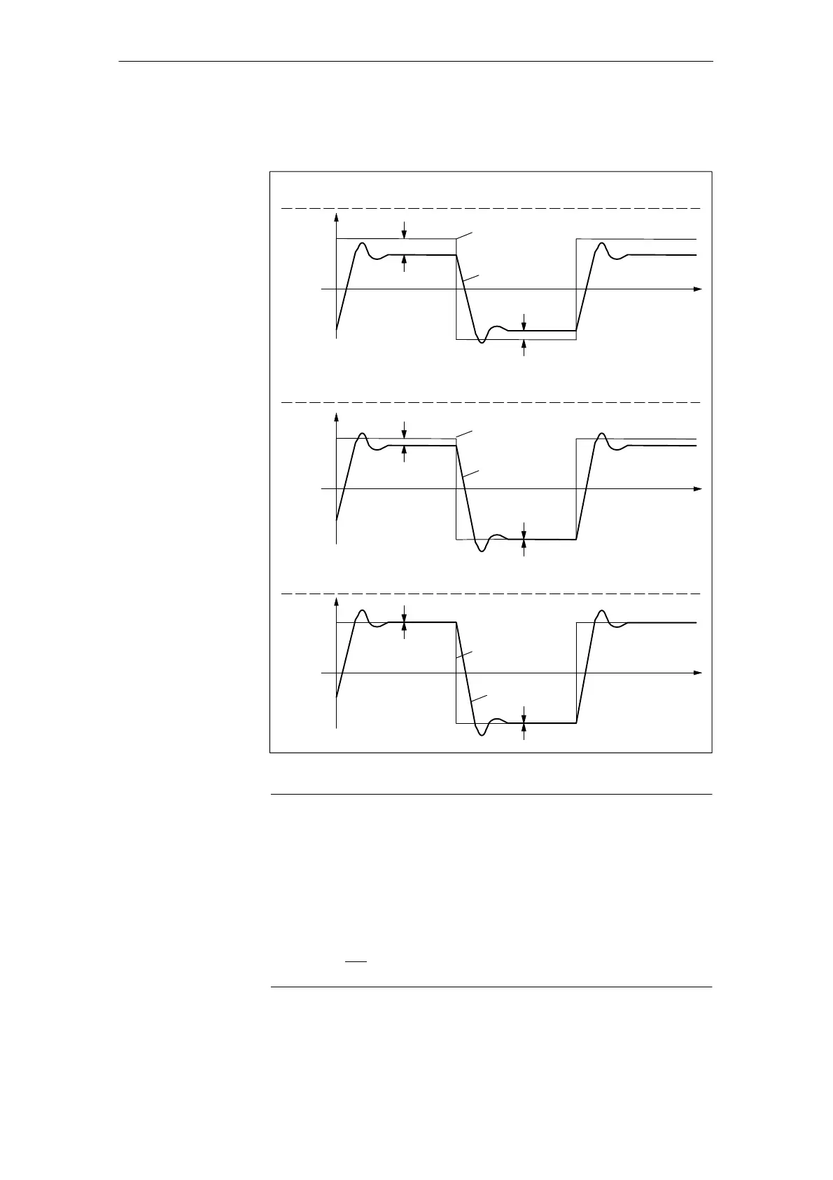
Use function generator to enter a velocity setpoint of v
set
,
offset=0.
Cylinder
travel-out
Cylinder
travel-in
∆
1
∆
2
t
v
Output curve behavior ∆
1
0 ∆
2
Controller=0; D, I, P
Aim of adjustment ∆v
out
= 0
∆v
in
= 0
Adjustment stage 1: Identical setting for both velocity directions with
MD 5435; match v
set
and v
act
at one end.
Cylinder
travel-out
Cylinder
travel-in
∆
1
∆
2
= 0
t
Adjustment stage 2: Direction-dependent adjustment with MD 5462 and/or
MD 5463.
Cylinder
travel-out
Cylinder
travel-in
∆
1
= 0
∆
2
= 0
t
v
set
v
v
v
set
v
set
v
act
v
act
v
act
3. Adjusted state
Fig. 3-20 Adjustment of controlled system gain
Note
S V
set
is not represented by the “servo trace” function if the setpoint is defined
by the function generator.
S The setting must be checked at different velocities.
- Generally speaking, the average value of the calculated controlled
system gain must be set or
- the gain can be adjusted to match the relevant operating range.
S Both adjustment are equivalent, i.e. adjustment by the stage 2 method via
MD 5462 and
MD 5463 produces equivalent results when the preset value
(setting) of the controlled system gain (MD 5435) is applied.
Adjustment of
controlled system
gain
04.00
 Loading...


